Mbot Wiring
Last Updated: Sep 09, 2024
This guide is for Differential Drive MBot Classic.
Contents
1. Assemble 3 plates
| Components | # |
|---|---|
| 3-heads jumper wire cable | 1 |
| 4-40 thumb screw 3/8” | 8 |
-
Plug the 2-pin header into the control board.
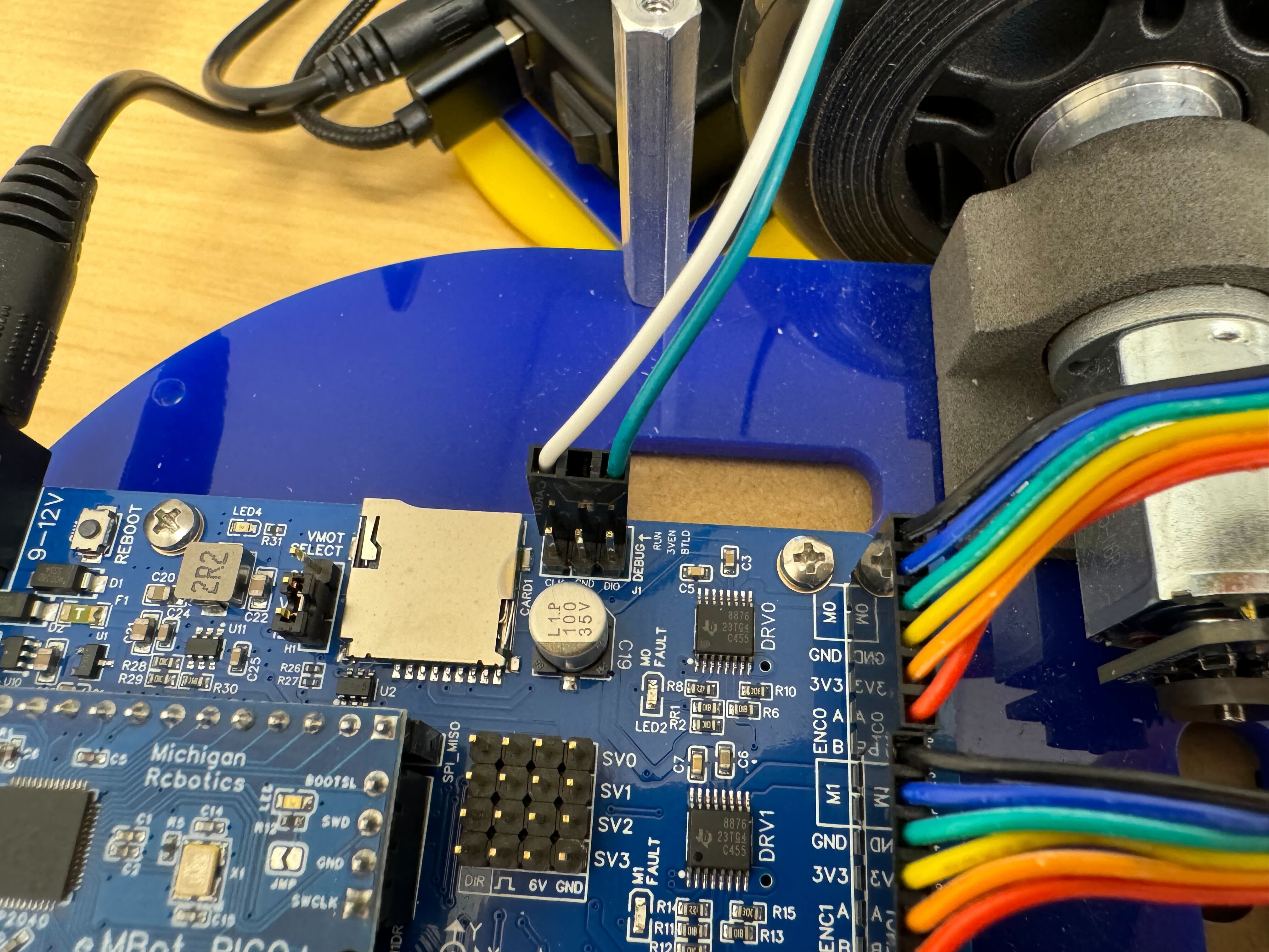
- White cable to RUN
- Green cable to BTLD
Next, pull the cable out through the front hole on the left side of the middle plate. Then, use the thumb screws to attach the middle plate to the bottom plate and secure the screws to the standoffs.
-
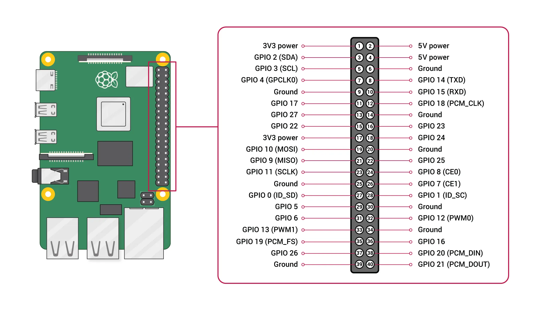
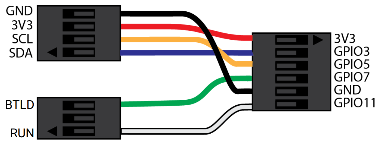
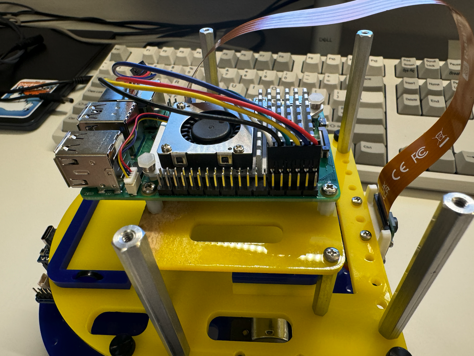
Plug the 6-pin connector into the Raspberry Pi pins.
According to the image below, the red cable should be connected to Pin 1 (the number inside the circle, not the number marked on the side), and the white cable should be connected to Pin 11.
-
Connect the 4PIN connector to the OLED, ensuring that the pins align with the marked positions.
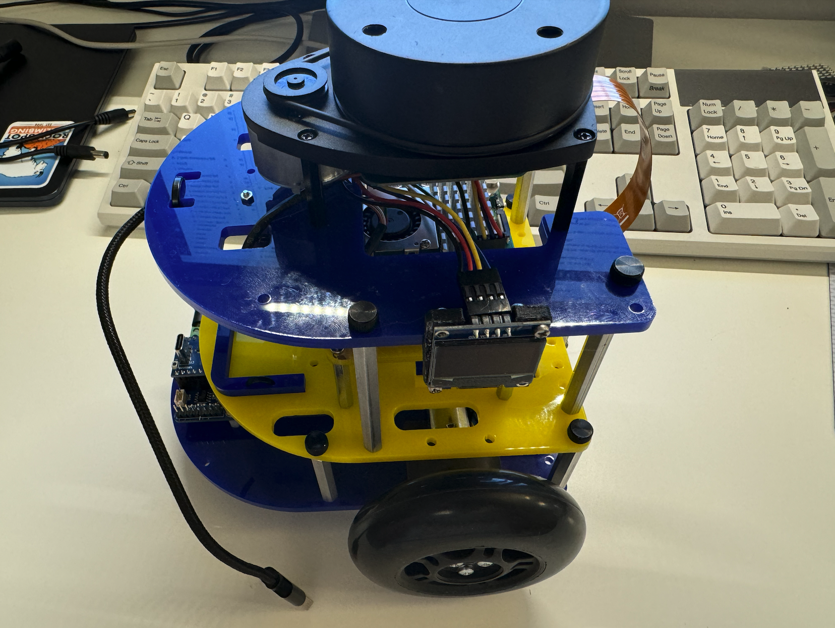
Then, use the thumb screws to attach the top plate to the middle plate and secure the screws to the standoffs.
2. Final Wiring
| Components | # |
|---|---|
| 12V Power Bank | 1 |
| DC power “Y” cable with rounded ends | 1 |
| USB-C Cable | 2 |
- “Y” Cable: Connects the power bank to the Robotics Control Board, providing power to the control board.
- USB-C Cable: Connects the power bank to the Raspberry Pi, supplying power to the Pi.
- USB-C Cable: Connects the Robotics Control Board to the Raspberry Pi for communication between the Pi and the control board.
- Lidar’s USB: Connects to the Raspberry Pi’s USB port.
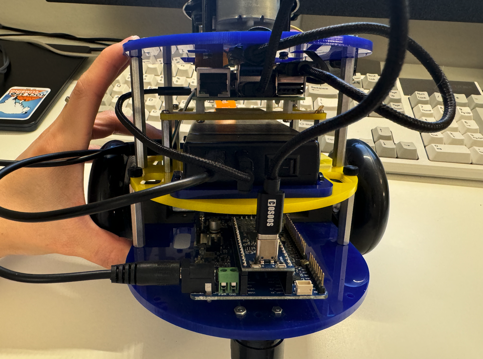
Raspberry Pi 5 power supply slot is on the side:
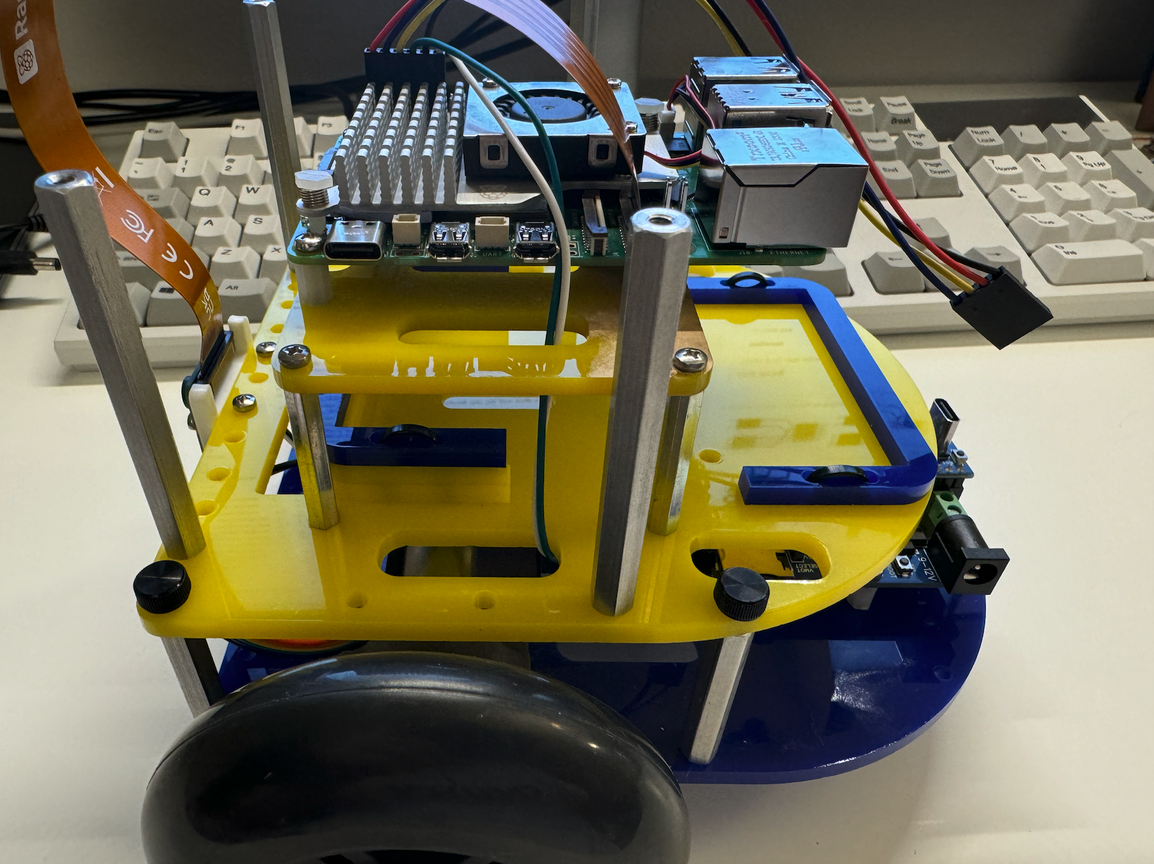
The final result should look like this:
Now you have a complete version of MBot!