Bottom Plate
Last Updated: Sep 03, 2024
This guide is for Differential Drive MBot Classic.
You might have encoders that are not covered in this guide. Here we only included resolution 40 encoder.
Contents
- Contents
- 1. Mount the caster
- 2. Mount the motor brackets
- 3. Mount the motors
- 4. Mount the short 1.5” aluminum standoffs
- 5. Attach the wheels
- 6. Assemble the Control Board
- 7. Connect the wires to Robotics Control Board.
- 8. Attach the Control Board to the bottom plate
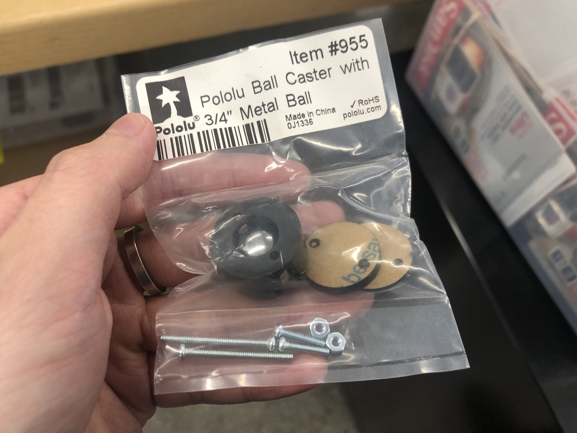
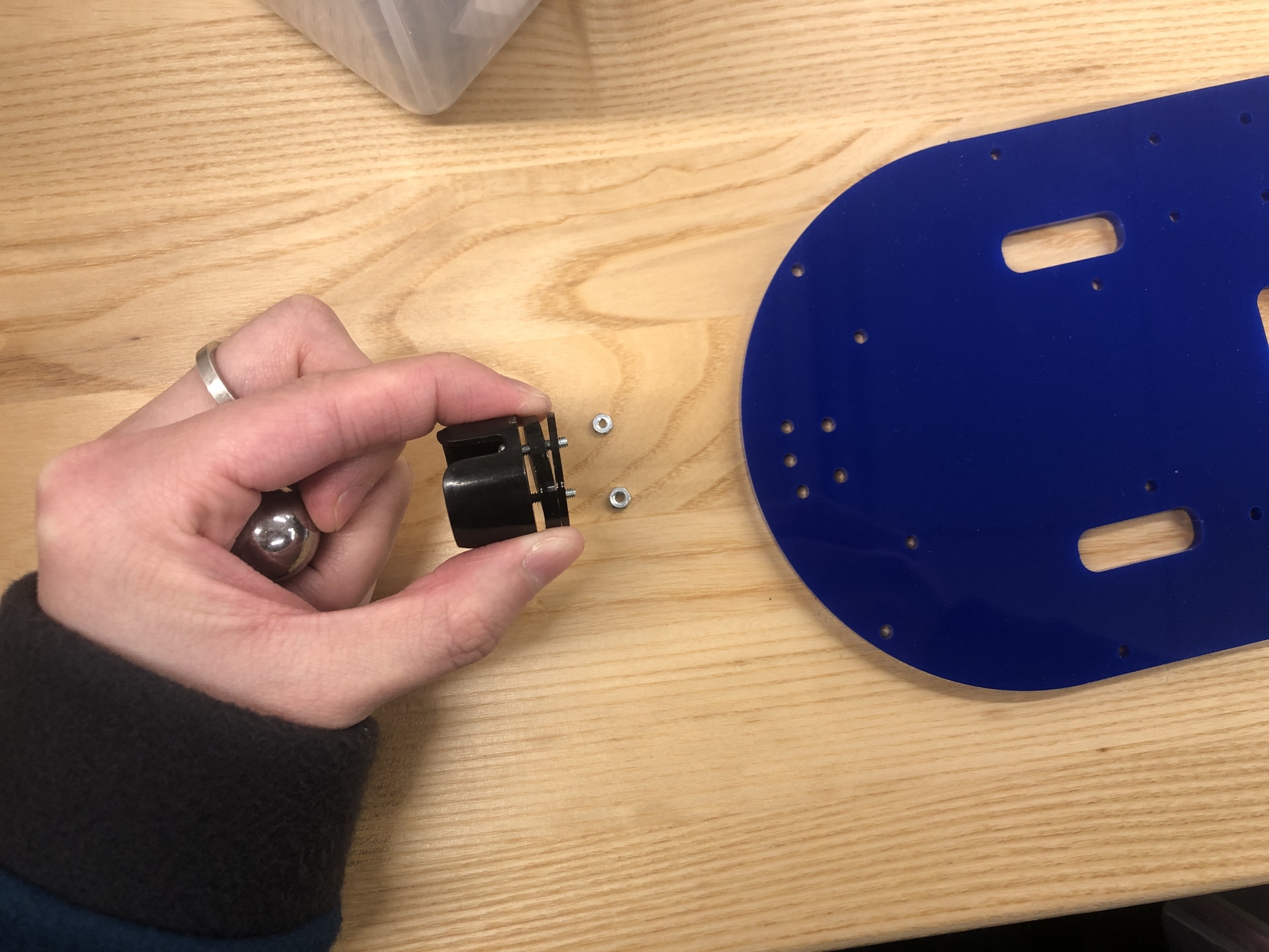
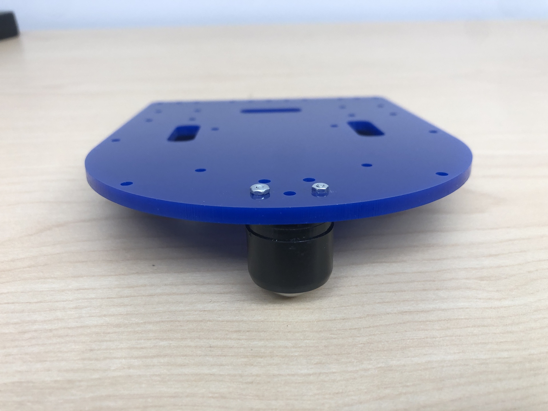
1. Mount the caster
| Components | # |
|---|---|
| Metal ball | 1 |
| Bottom Acrylic Sheet | 1 |
| 1/8” spacer | 1 |
| 1/16” spacer | 1 |
| M2 hex nuts | 2 |
| M2 x 12mm screw | 2 |
| Caster housing | 1 |
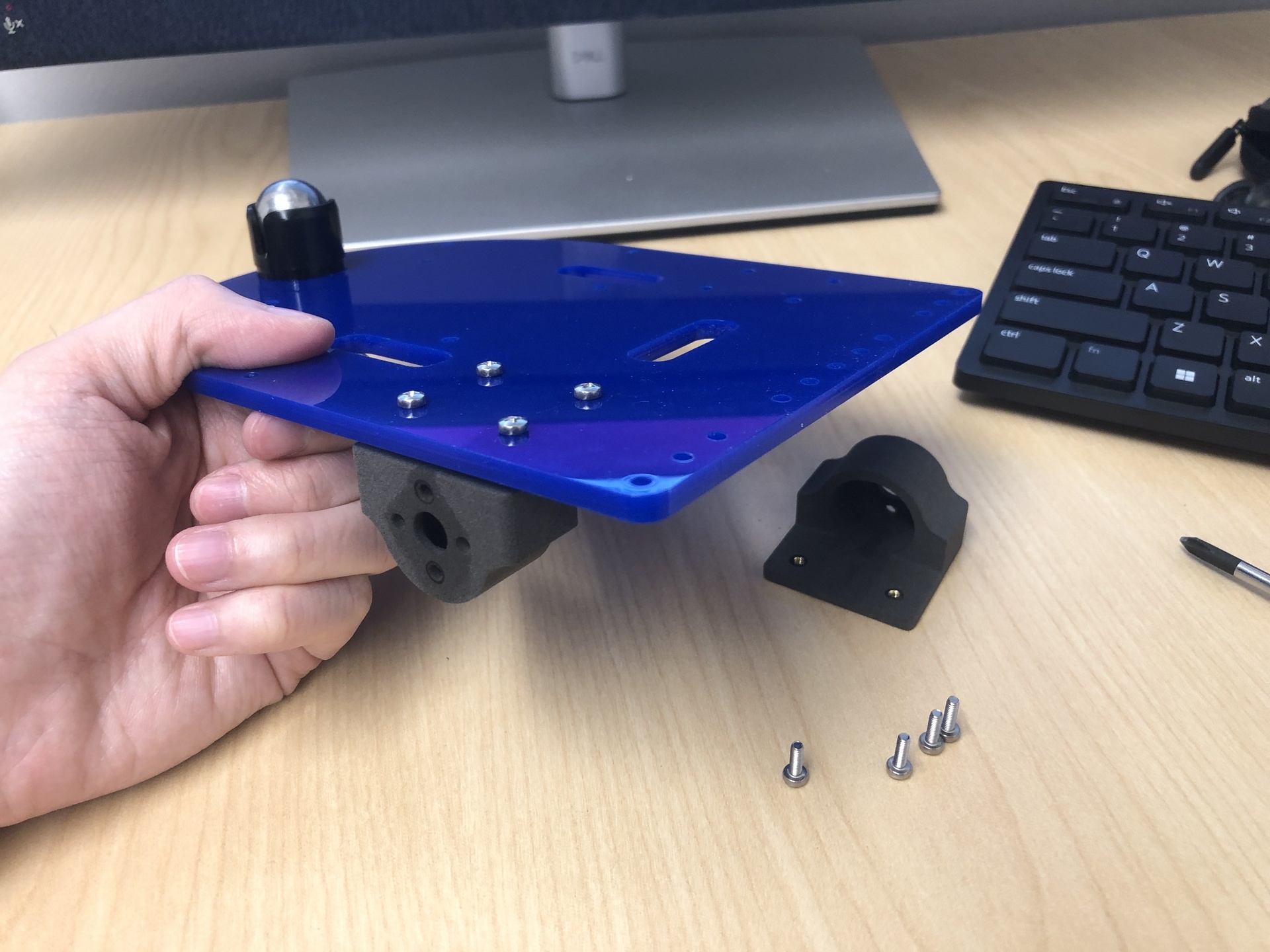
Gather all required components and assemble them as depicted in the images below. You’re not supposed to use the screws that come with the caster. Instead, search for M2 x 12mm screws to put it all together. You need to stack both spacers one on top of another during your assembly in order to match the height of the wheels.
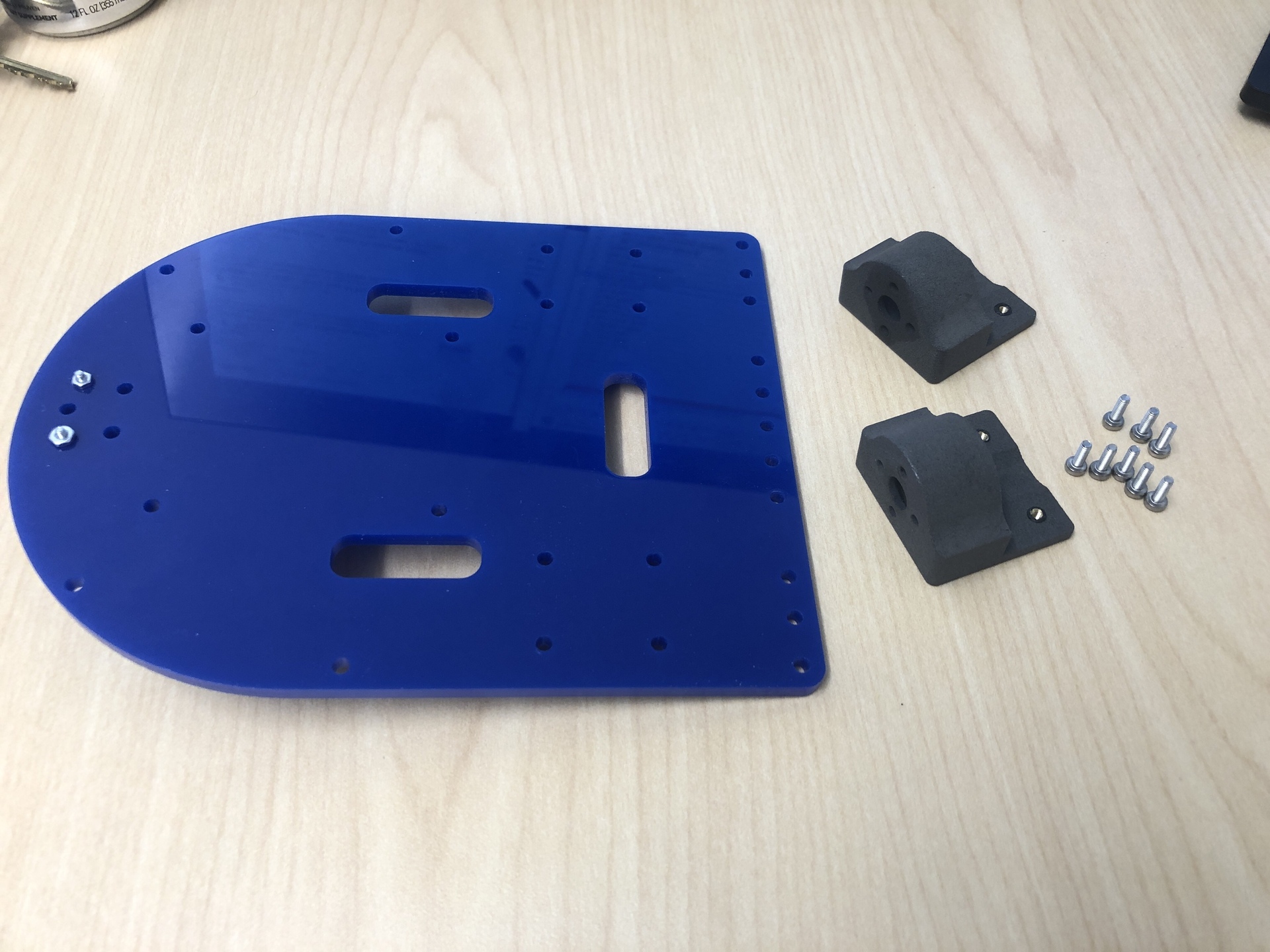
2. Mount the motor brackets
| Components | # |
|---|---|
| M2.5 x 8mm Screws | 8 |
| Motor Mount (3D printed) | 2 |
| M2.5 threaded inserts | 8 |
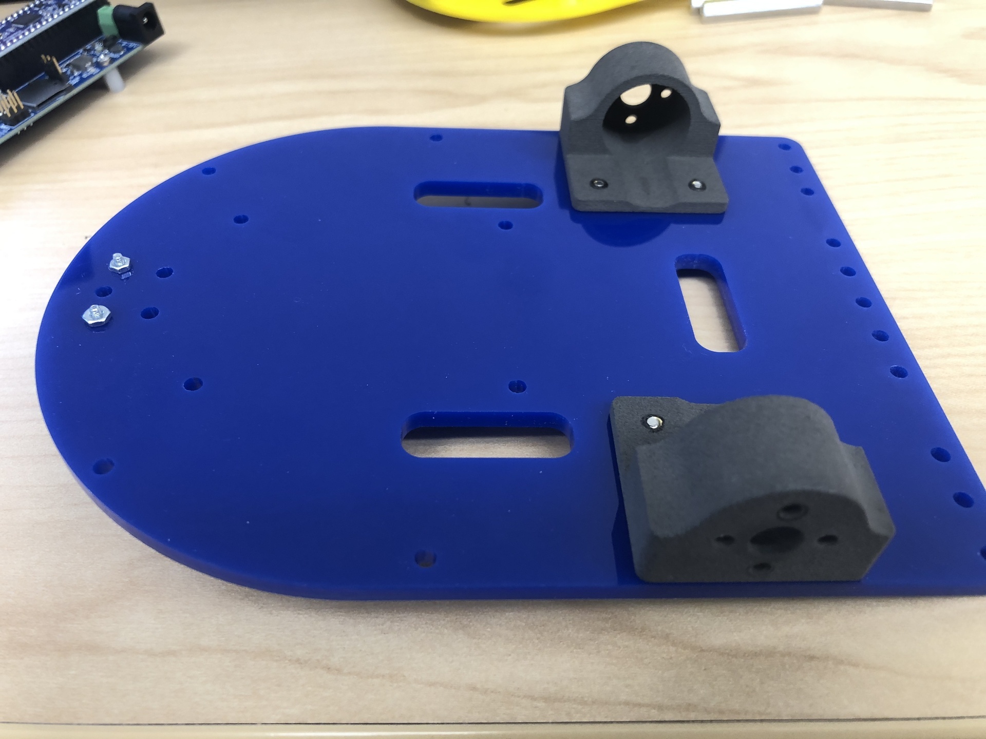
- Insert the threaded inserts into the motor mount’s bottom plate, you need soldering iron for this to heat up the inserts.
- Assemble them as illustrated in the images below. When attaching the mount to the bottom plate, ensure that the slot faces inward.
3. Mount the motors
Soldering Encoder
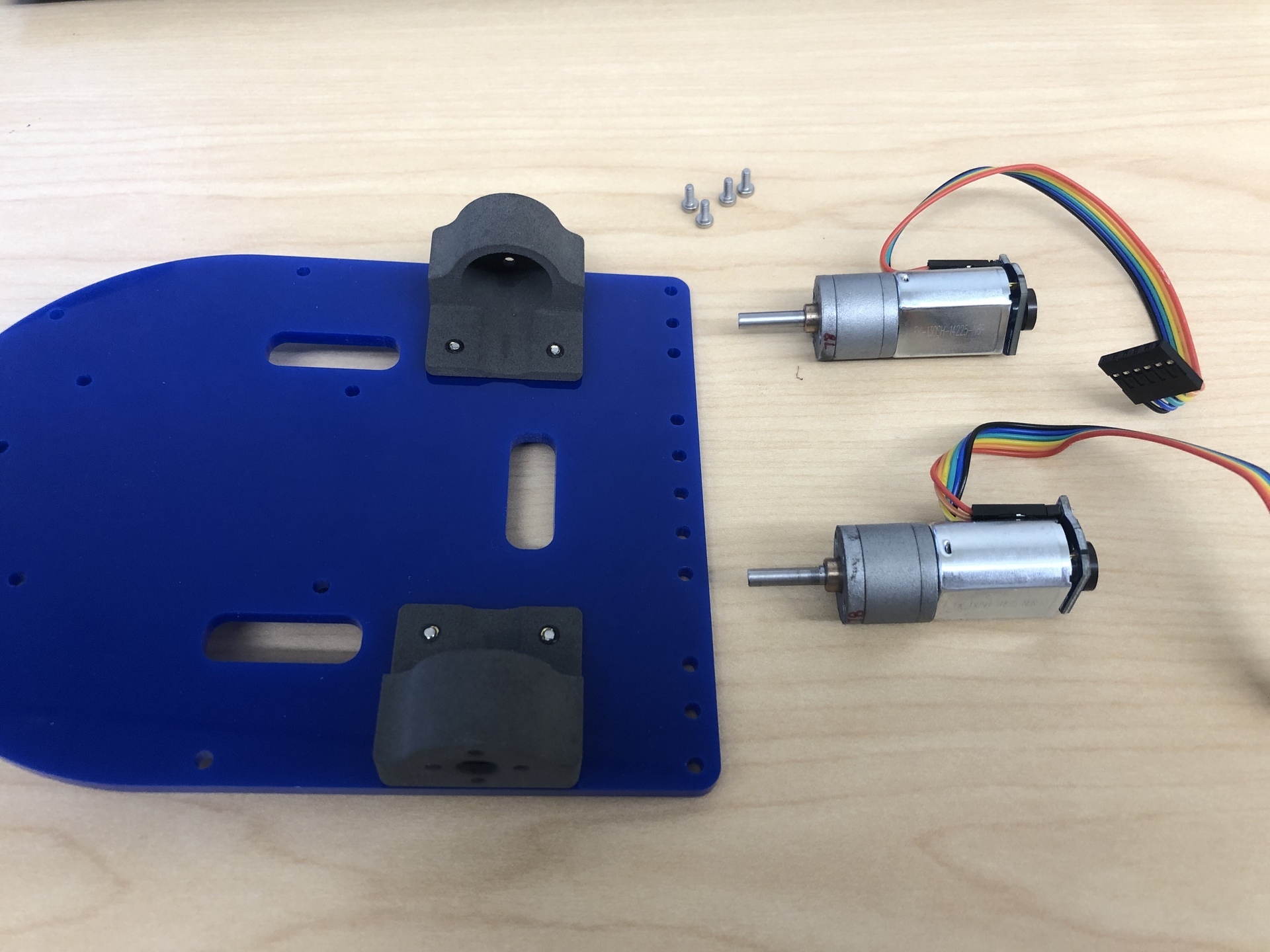
If your motor does not come with a pre-attached encoder, you will need to solder an encoder onto the motor yourself.
| Components | # |
|---|---|
| Motor | 2 |
| Encoder | 2 |
| Magnets | 2 |
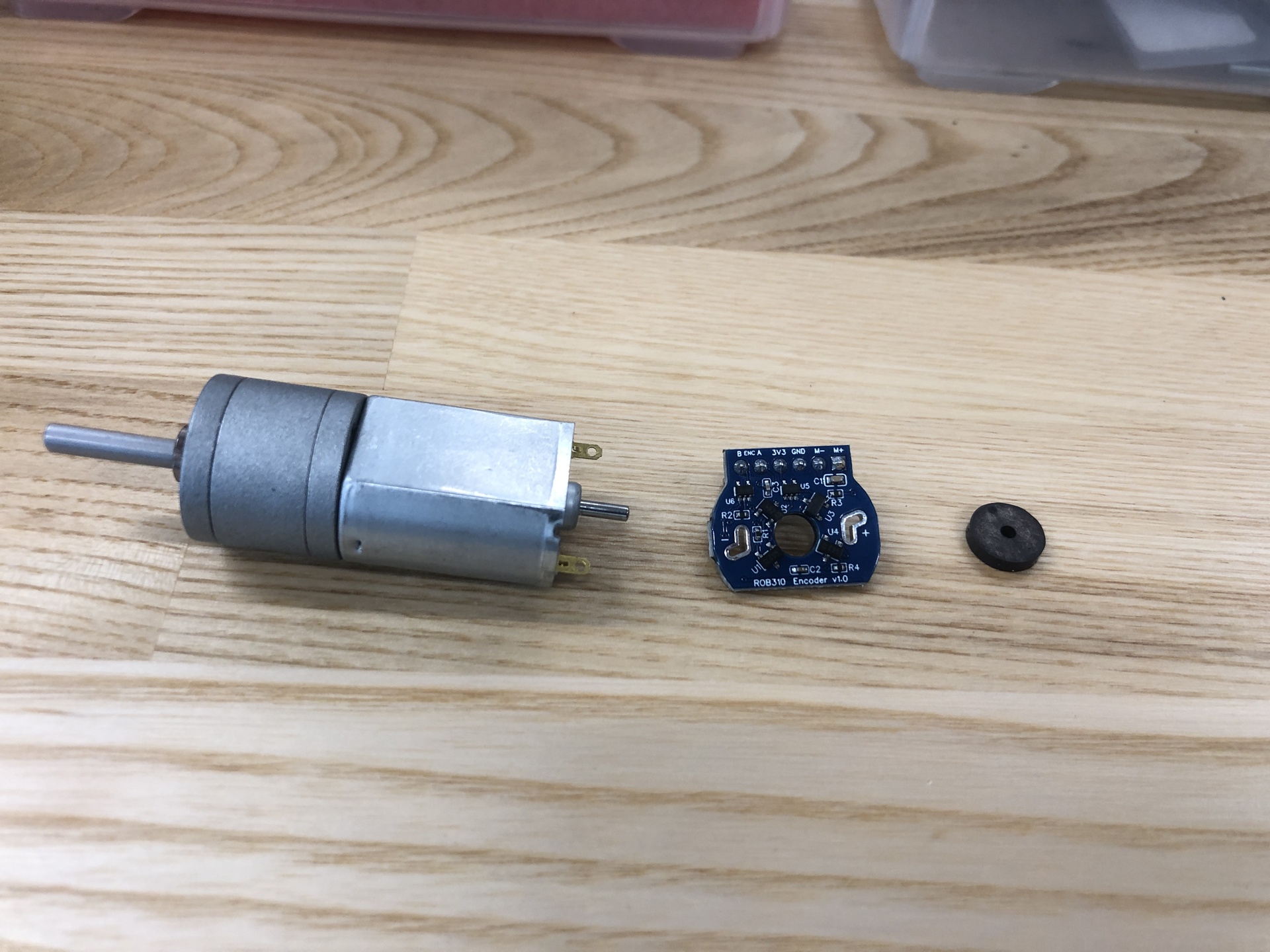
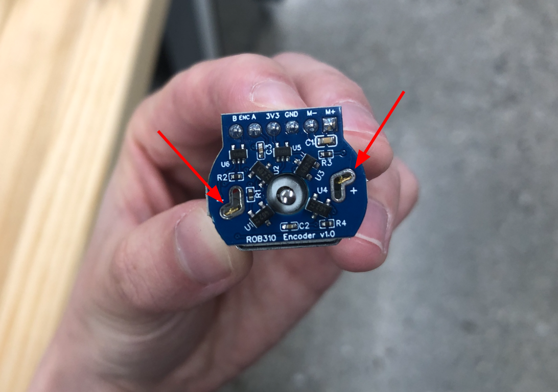
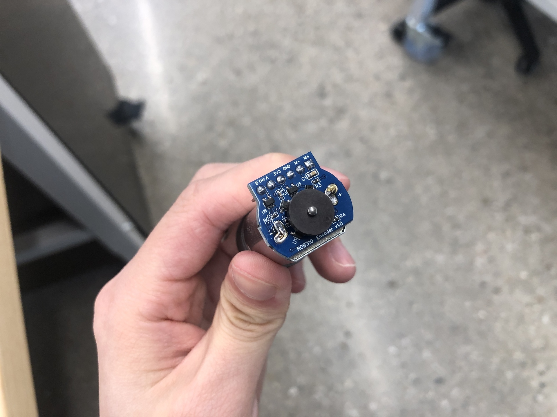
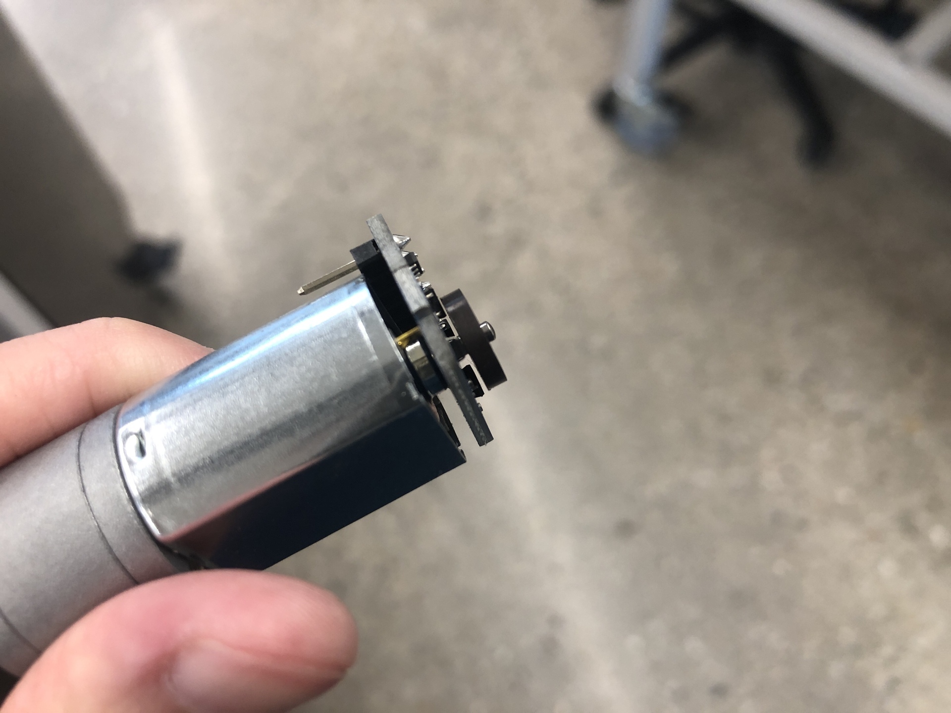
First, before assembling all the parts, you need to solder the encoder to the motor, as demonstrated in the 2nd image below. The 3rd image displays the soldering result, and the 4th image shows the magnet’s placement. Please note that you should avoid positioning the magnet too close to the encoder or too far away, maintain a reasonable gap.
| Components | # |
|---|---|
| M2.5 x 6mm Nylock Screws | 4 |
| Gear Motors w/ Wiring & Encoders | 2 |
| 6-PIN jumper wires | 2 |
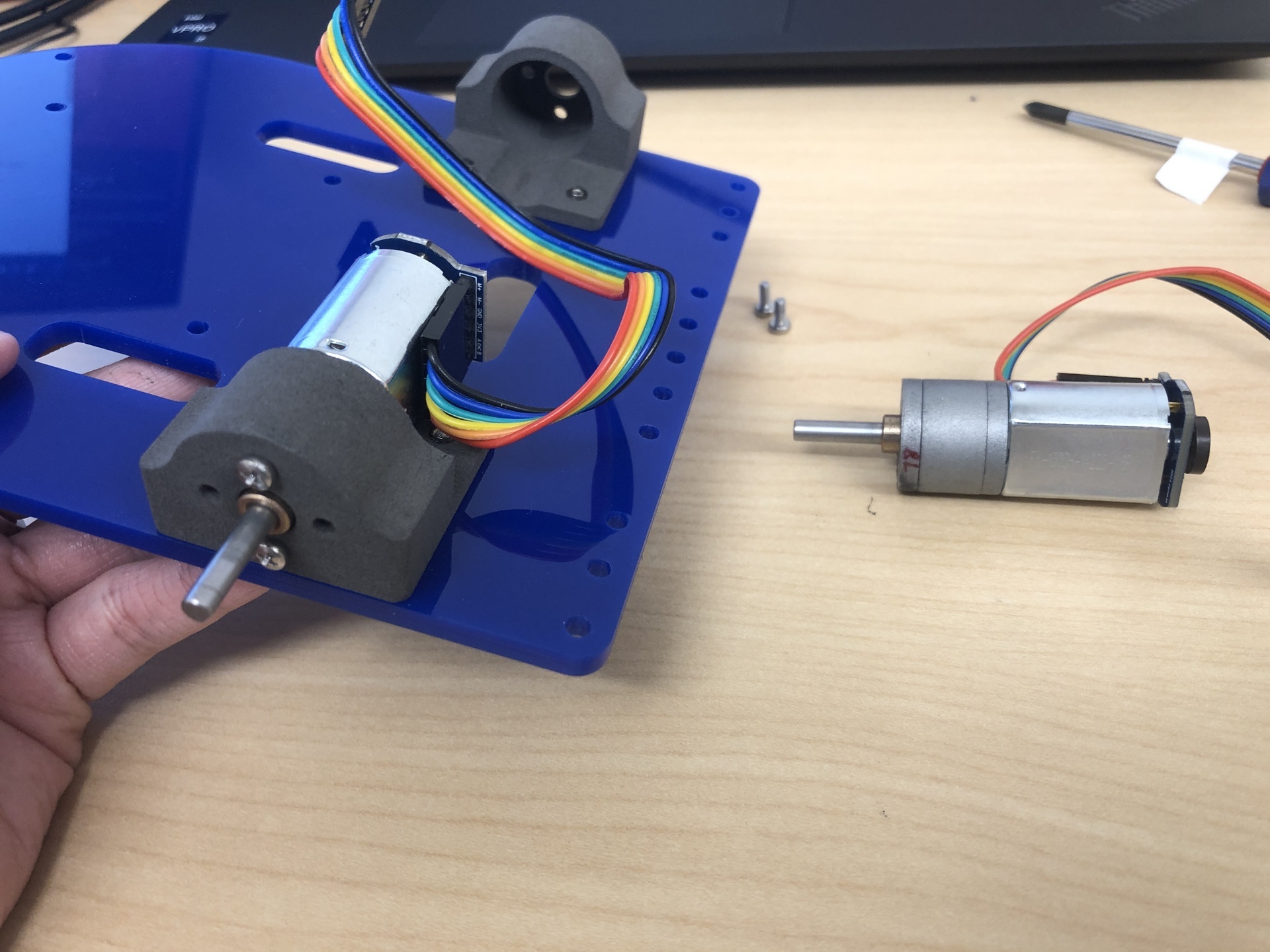
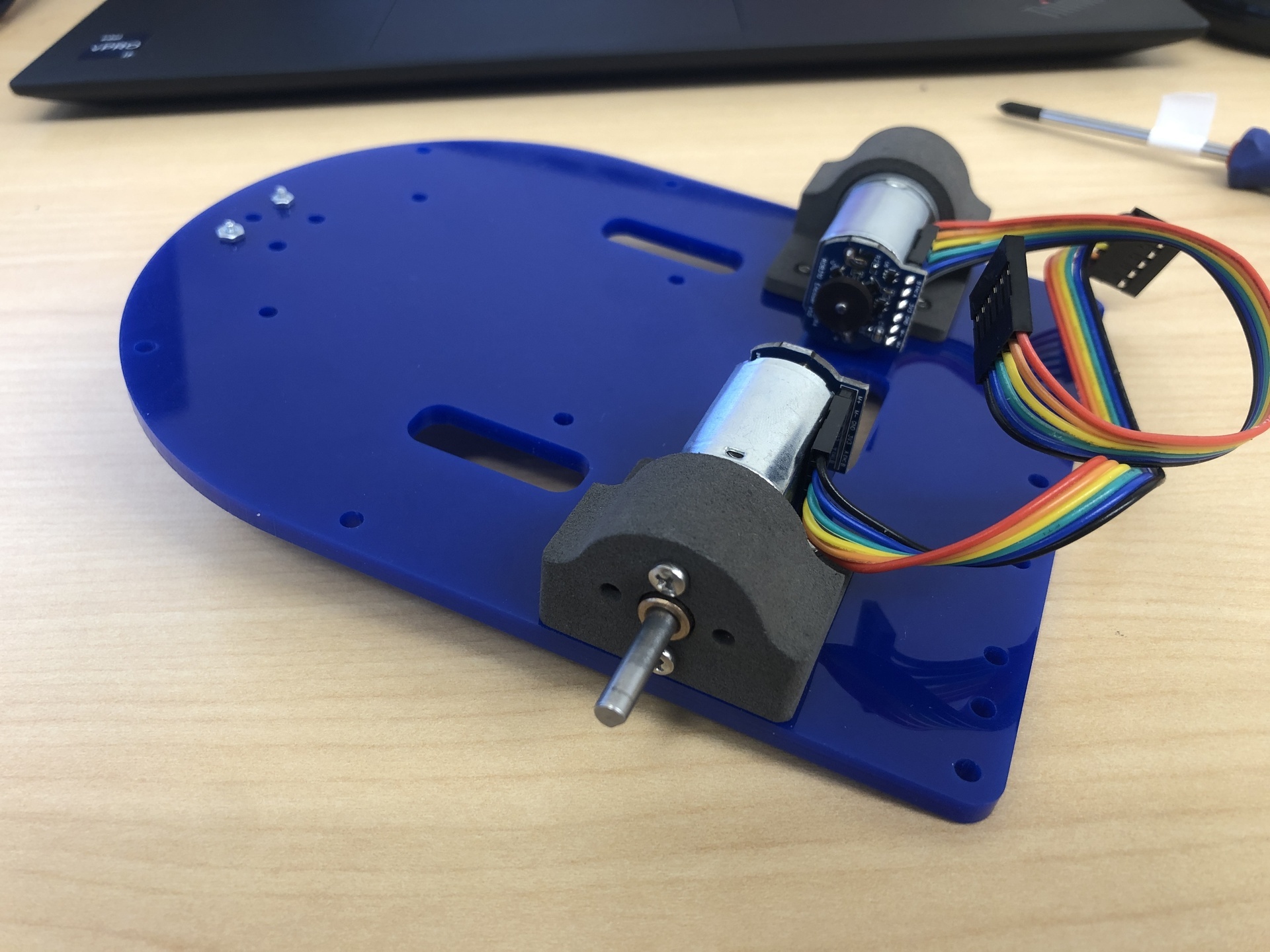
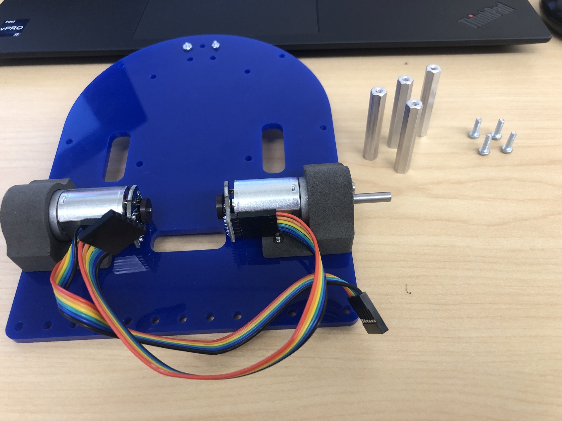
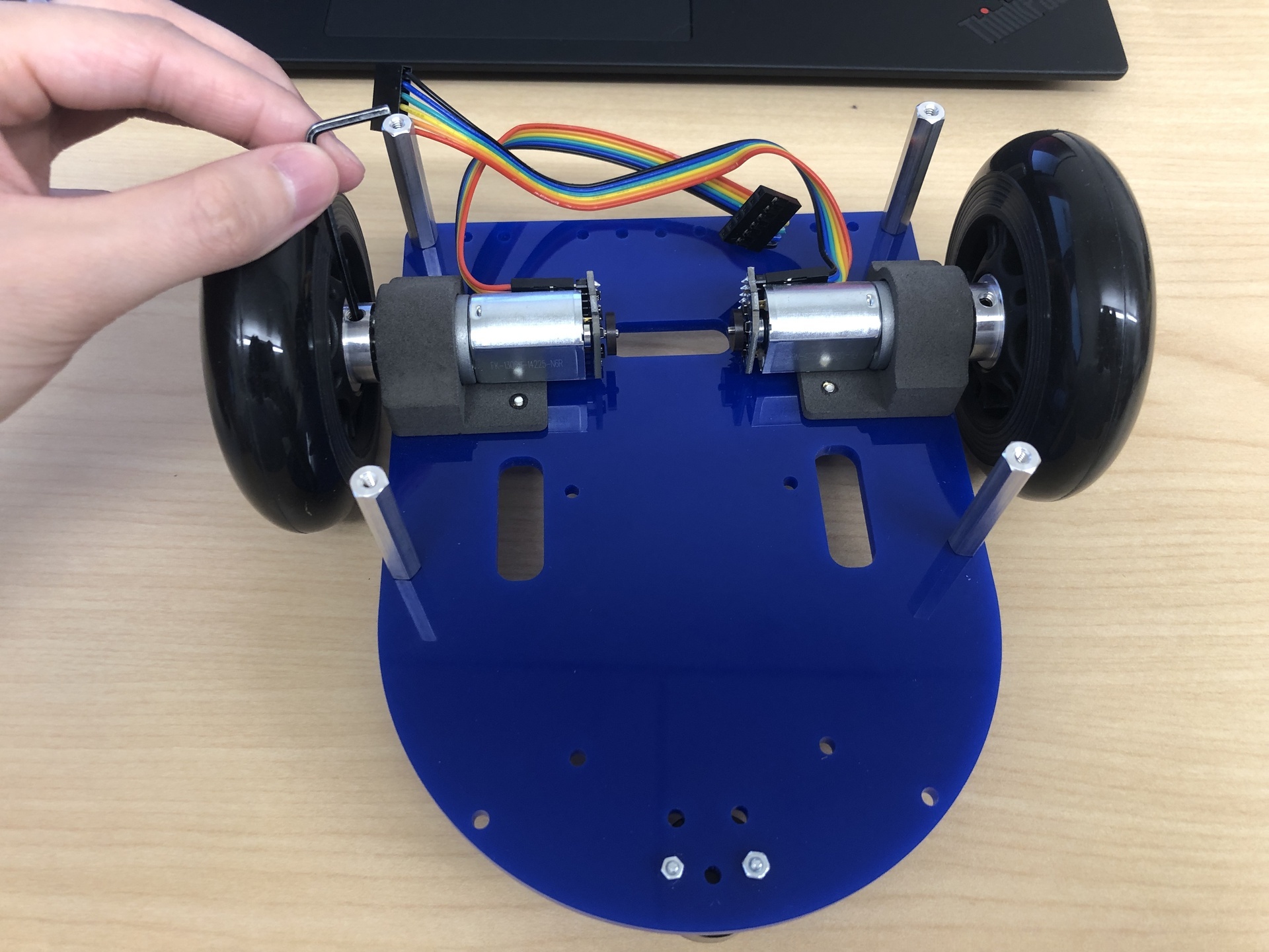
If your motor has pre-attached encoder, firstly connect the jumper wires to the motor’s pin as shown in the 1st image. Note that you need to align unthreaded holes in motor vertically to the holes in the motor mount, while the wires should face the back of the MBot as shown in the second figure.
4. Mount the short 1.5” aluminum standoffs
| Components | # |
|---|---|
| 4-40 x 1.5inch standoffs | 4 |
| 4-40 x 3/8inch screws | 4 |
Gather all the components and assemble as shown in the images below.
5. Attach the wheels
| Components | # |
|---|---|
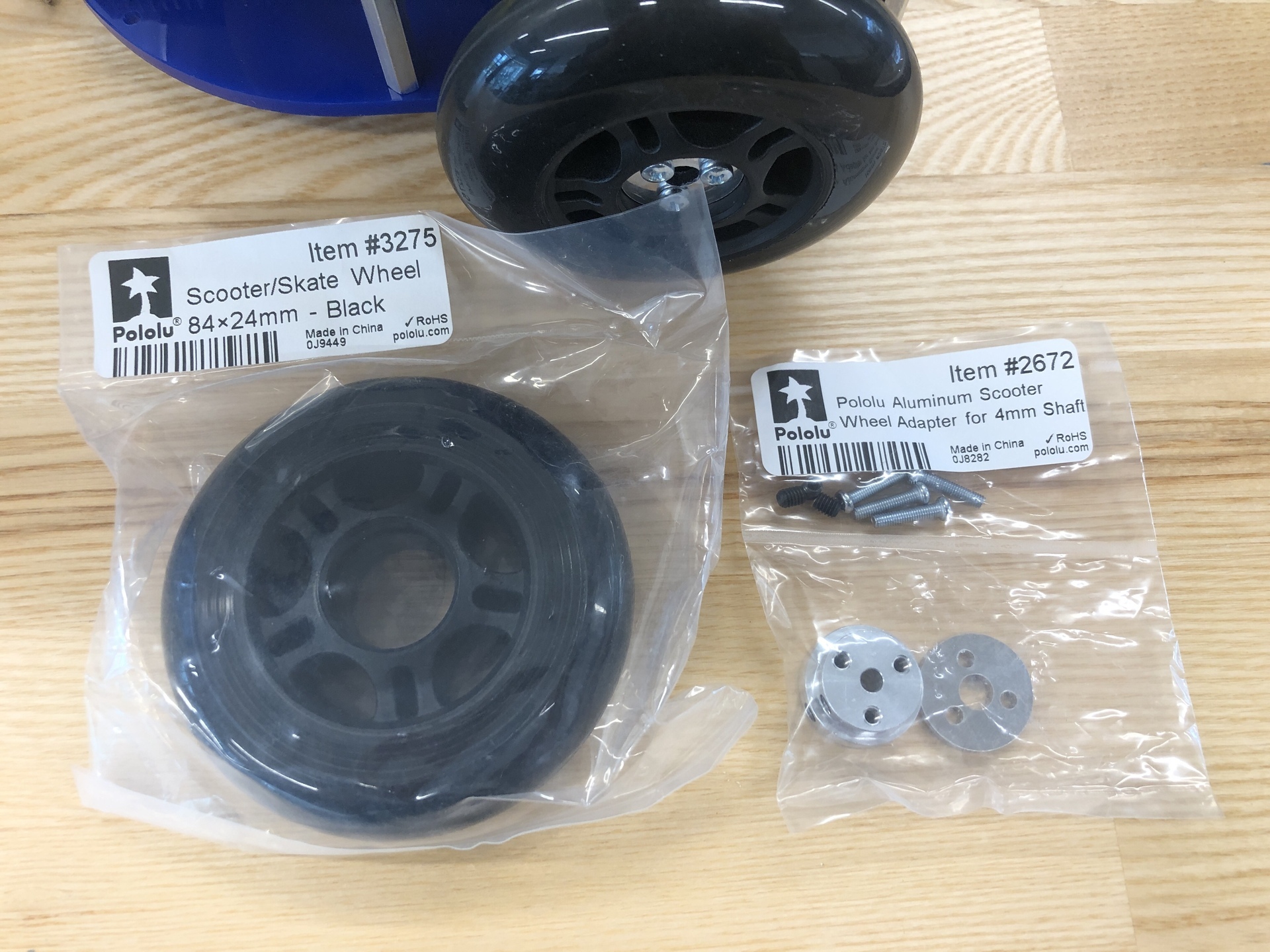
| Scooter Wheels 84 X 24 mm | 2 |
| M3x20mm screws | 6 |
| Wheel adapter | 2 |
| Set screws | 2 |
| Hex Key | 1 |
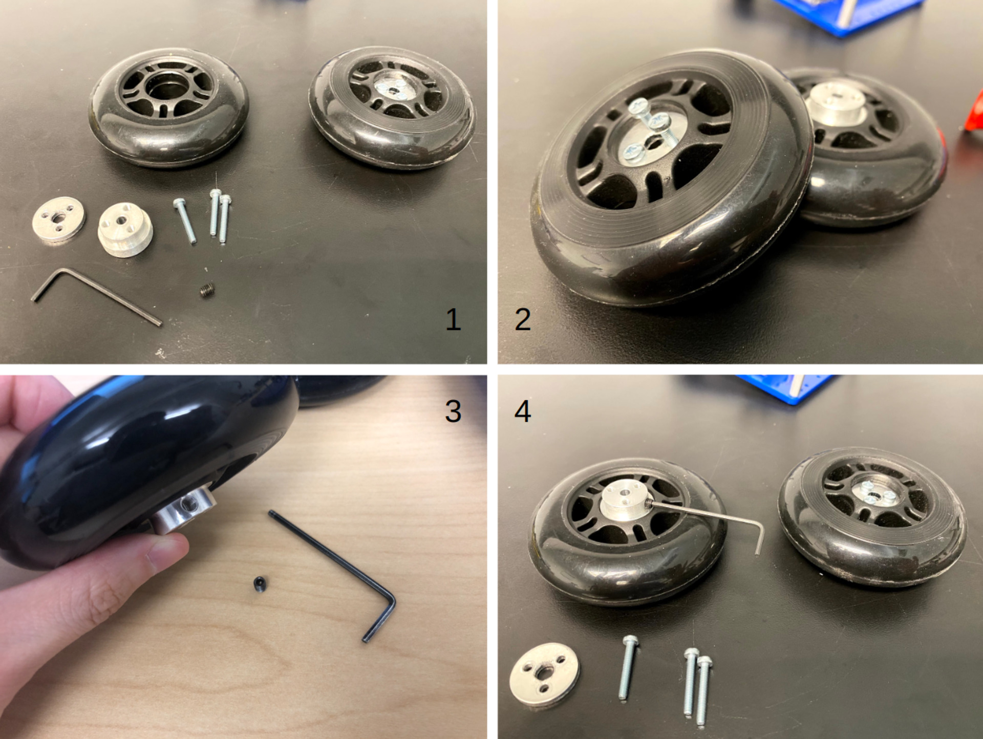
Note that we will not use the M3x14mm screws that came with the wheel adaptor, as they are not long enough, instead we are going to use M3x20mm screws here.
Follow the steps below:
- First, press fit the machined wheel adaptor into one side of the wheels, ensuring a part of it sticks out.
- Then press fit the flat metal piece into the opposite side, aligning the three holes.
- Insert the M3x20mm screws to secure the parts together, as demonstrated in the second image.
- Using the 2mm Hex wrench screw the set screws that come with the wheel adaptor kit into the wheel adaptors as shown in the 3rd and 4th image.
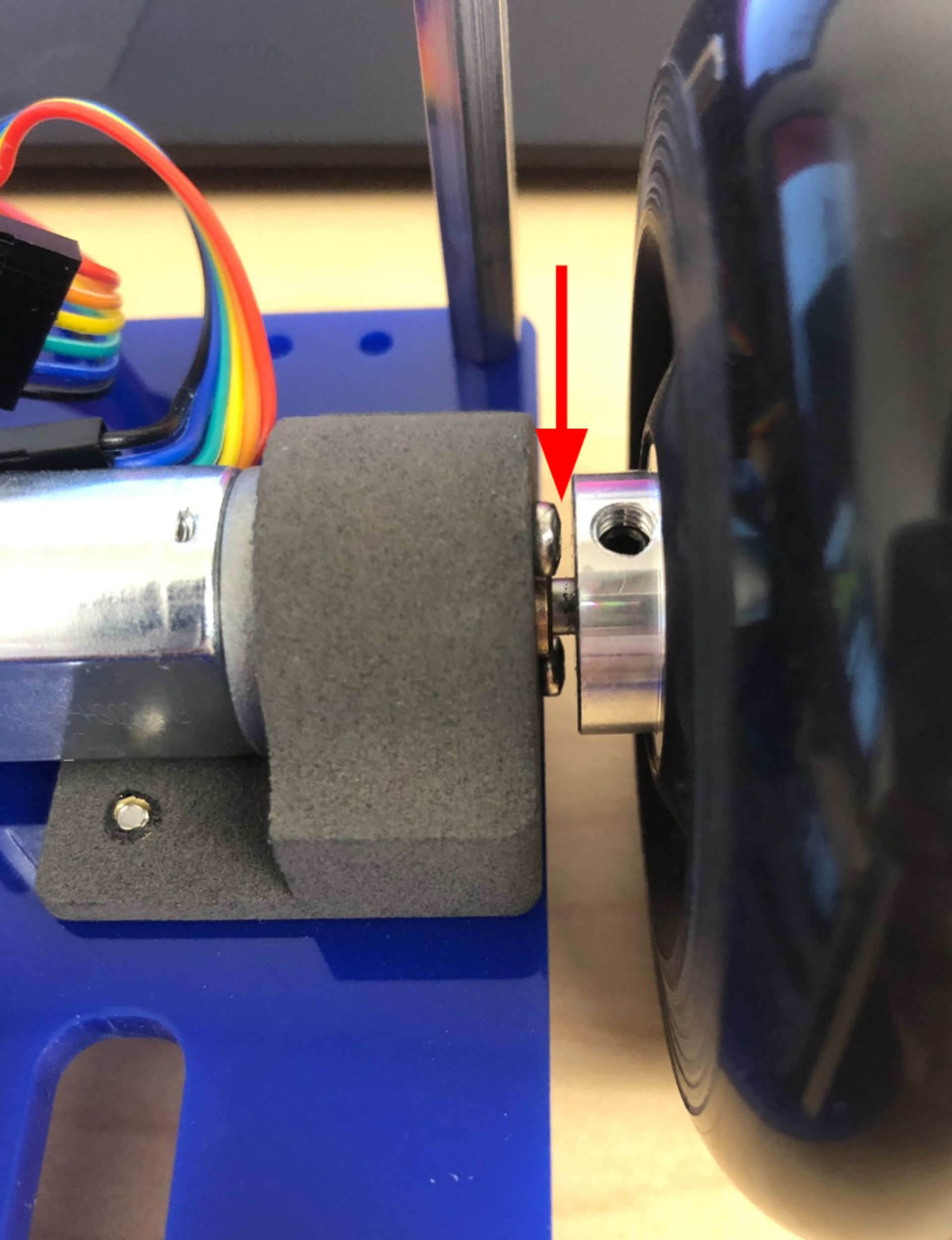
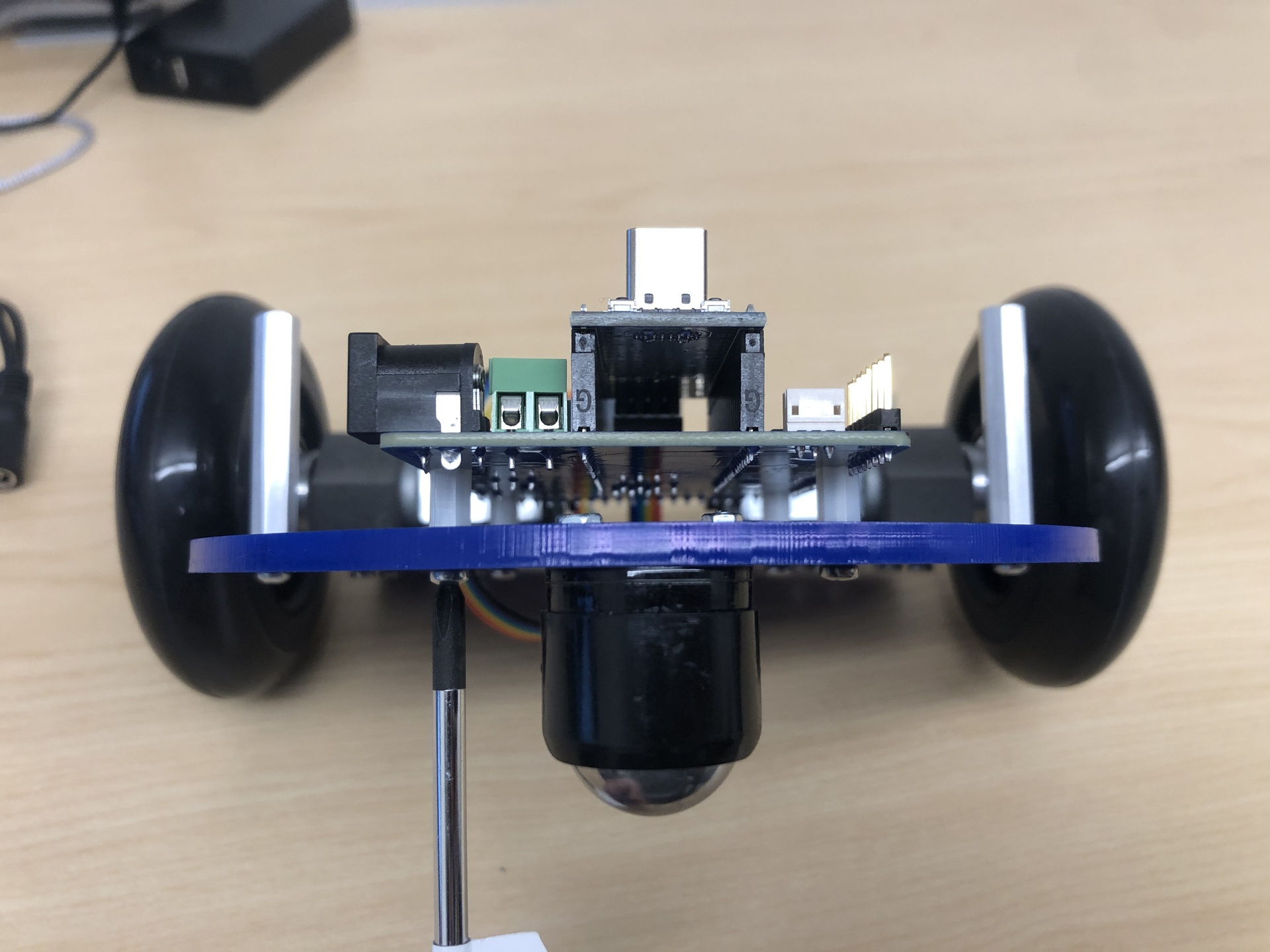
Then you can directly put the wheel on, use the hex key to tight the wheels. Note that it is necessary to leave a bit of space between the wheel and the screw head of the motor, as depicted in the image below, otherwise the wheel hub will rub against the screws holding the motor causing excess friction or jamming the motors.
6. Assemble the Control Board
| Components | # |
|---|---|
| Robotics Control Board | 1 |
| MBot PICO+ | 1 |
| M2.5 8mm Nylon Standoffs | 4 |
| M2.5 x 6mm Screws | 4 |
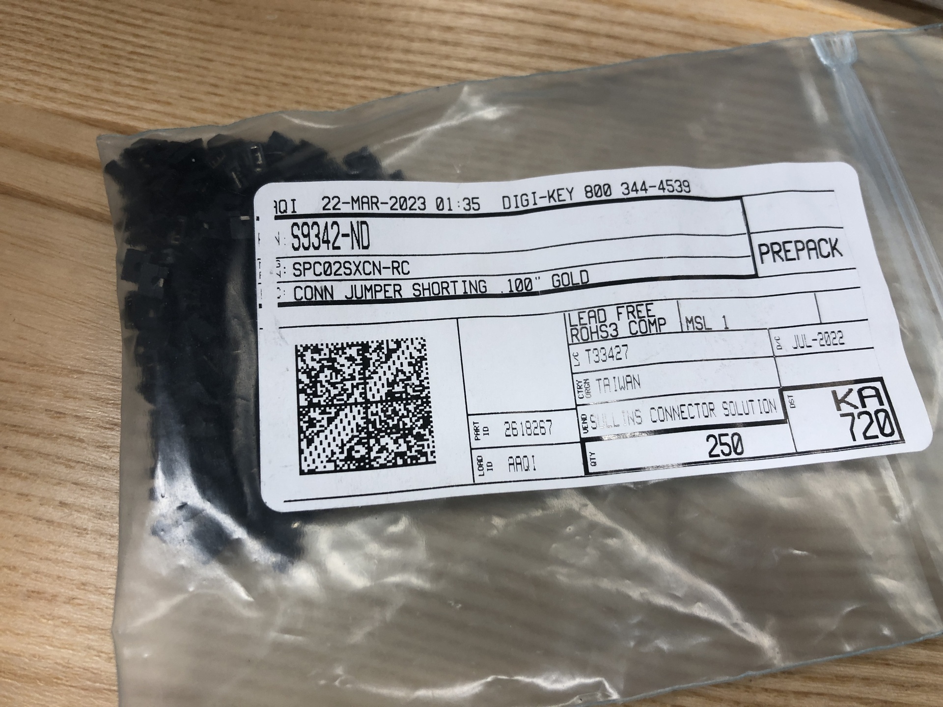
| Jumper Cap (Shorting block) | 1 |
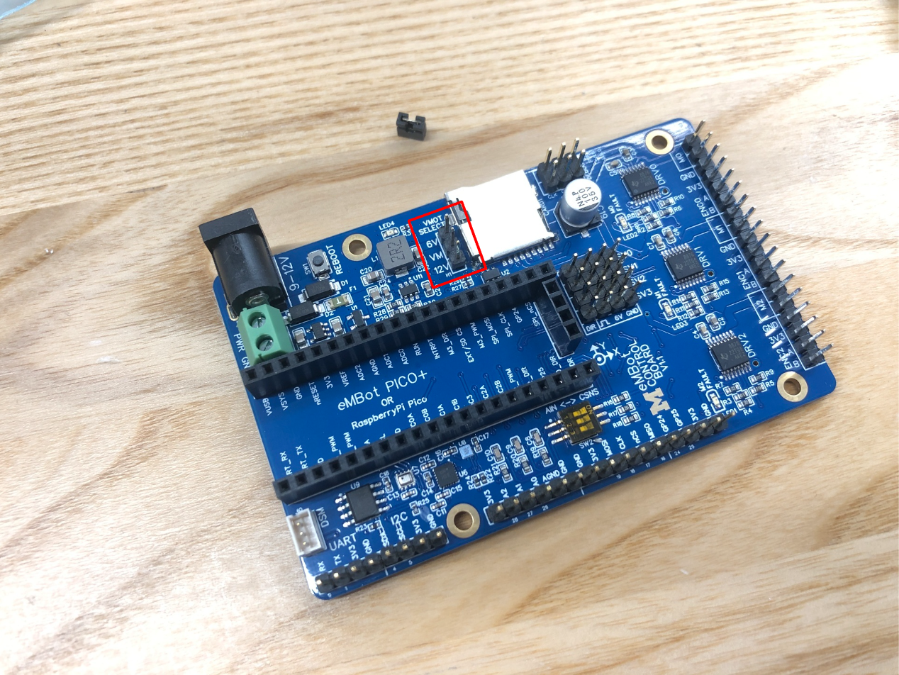
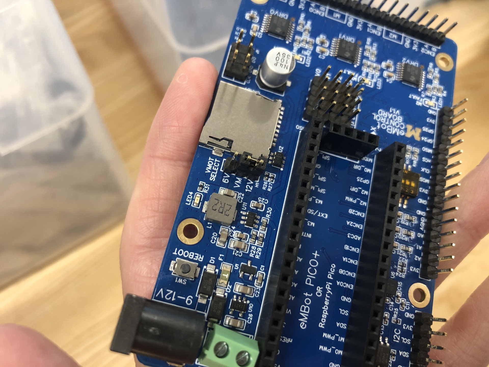
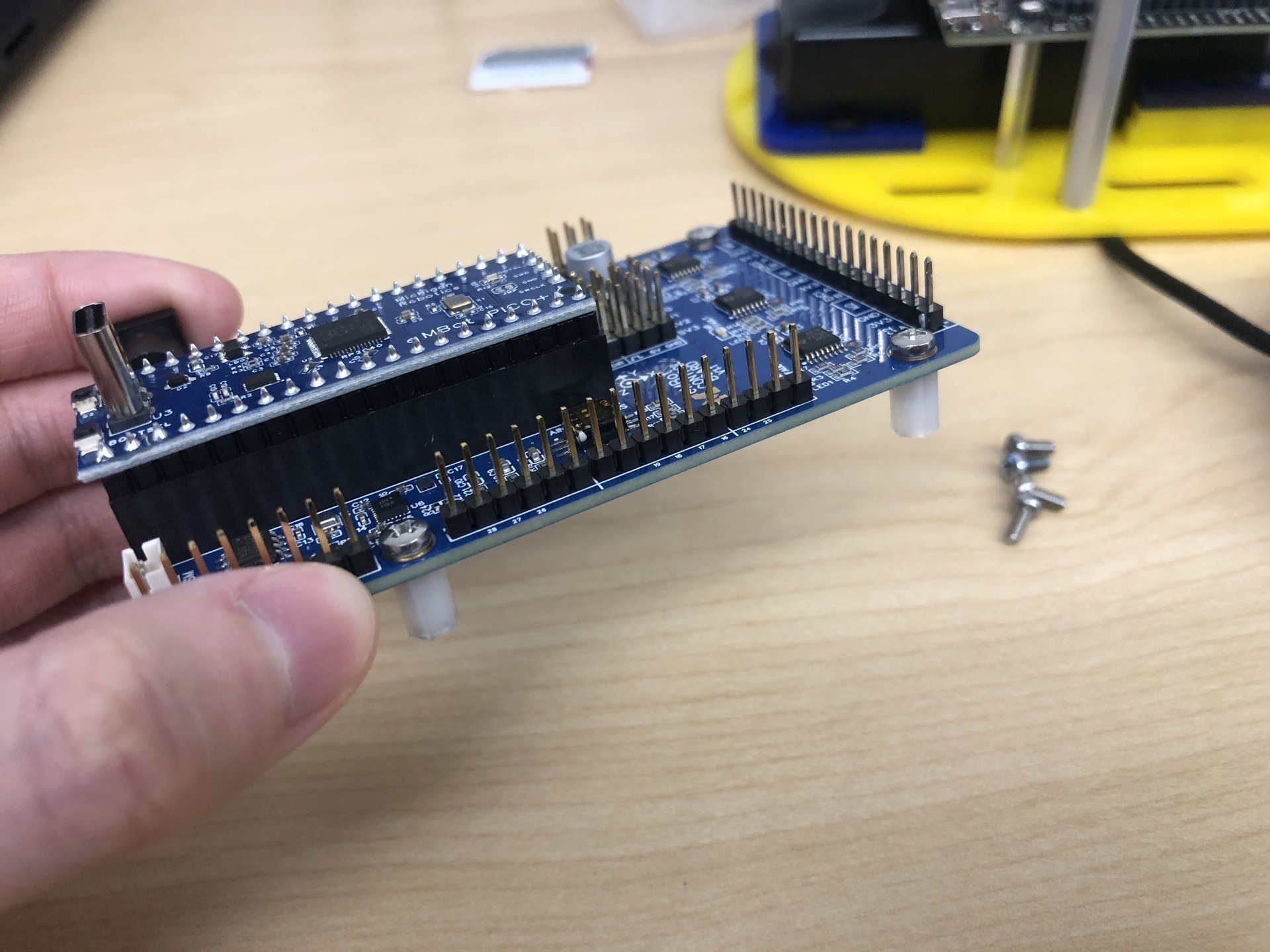
- Put the jumper cap on. Notice that in the 2nd image there are 3 pins squared together. Since we are using 12V, make sure to position the jumper cap over the VM and 12V pins, as demonstrated in the 3rd image.
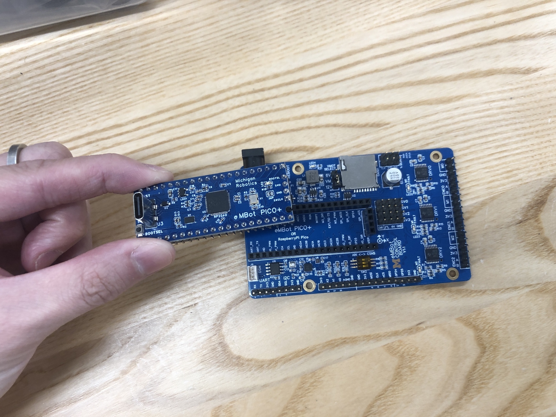
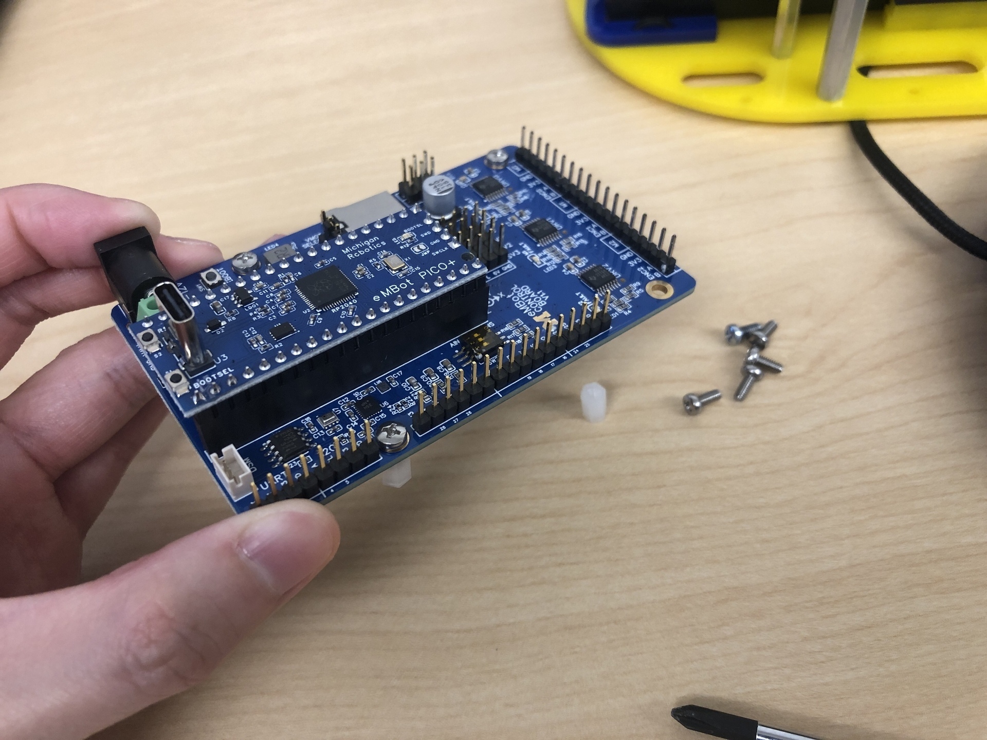
- Put the Pico and the standoffs on
7. Connect the wires to Robotics Control Board.
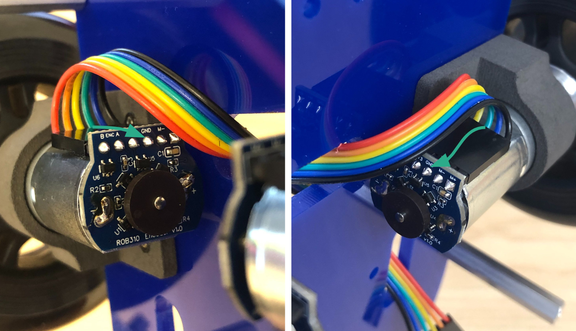
The rainbow cables have the following signals:
| Wire Color | Signal |
|---|---|
| Red | Encoder B |
| Orange | Encoder A |
| Yellow | 3.3 V |
| Green | GND |
| Blue | Motor- |
| Black | Motor+ |
-
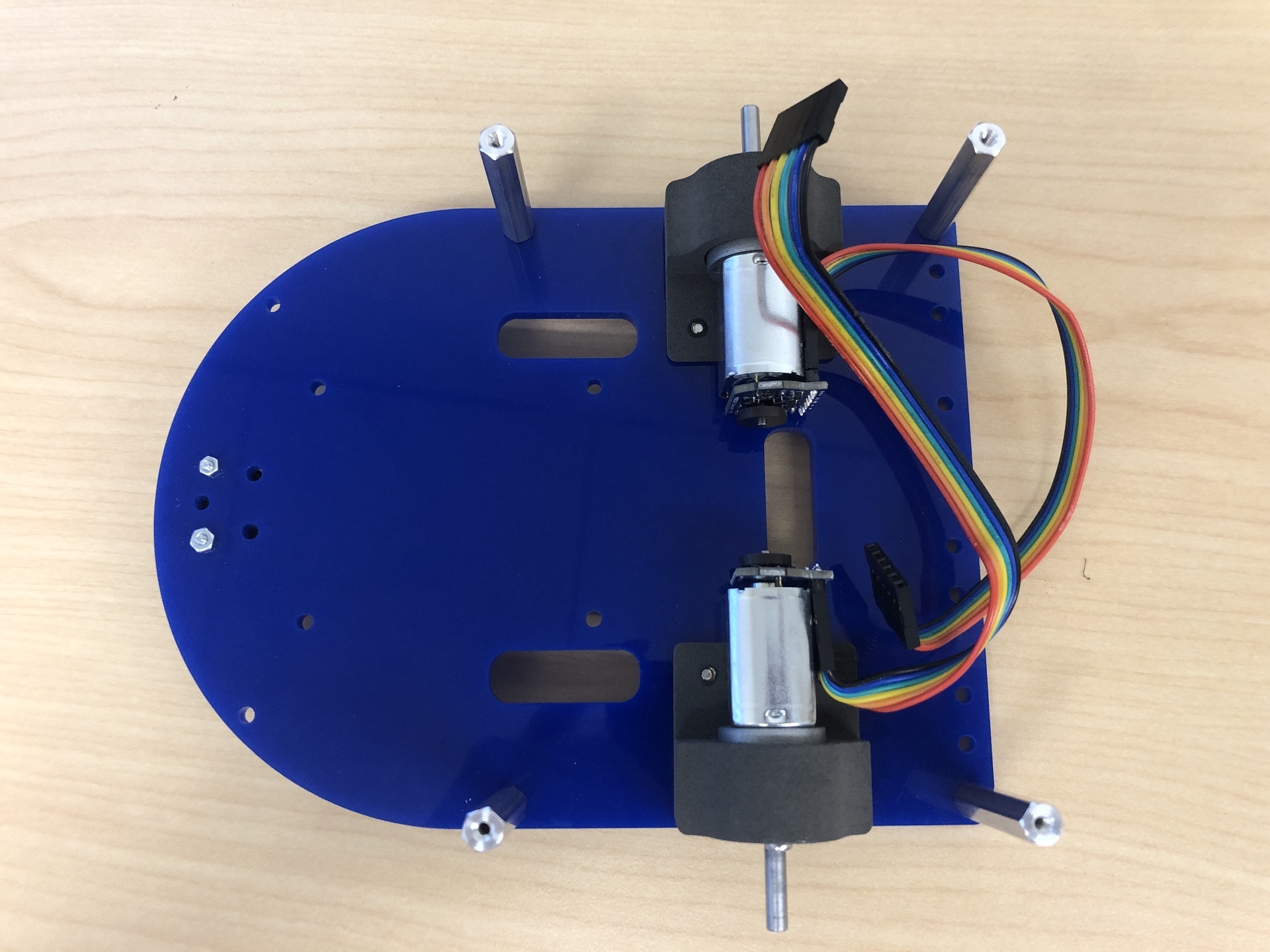
Examine the pins. In the case illustrated in the image, both the left and right motor have the green wire connected to the GND pin. We will use this info to connect to the Robotics Control Board.
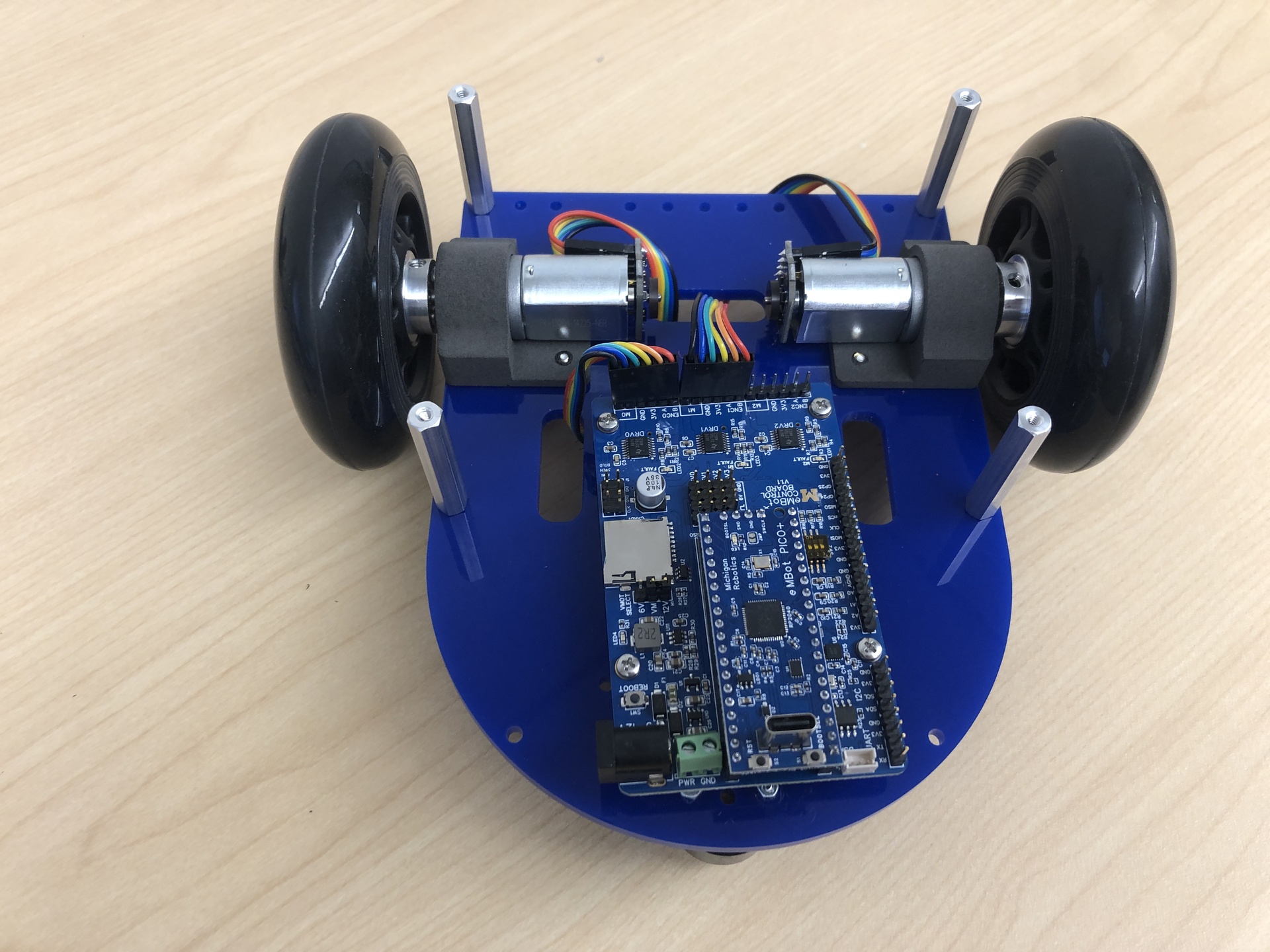
- Thread the wires through the bottom plate, following the configuration in the image below, ensuring they won’t interfere with the encoder’s magnet.
-
Identify the GND pin on the Robotics Control Board and connect the wires to it accordingly. In this case, the green wire is connected to the GND pin. Note that you should connect the left wheel to M0 slot, right wheel to M1 slot as shown in the image.
8. Attach the Control Board to the bottom plate
| Components | # |
|---|---|
| M2.5 x 6mm Screws | 4 |
If you have successfully assembled the bottom plate, the result should look like this:
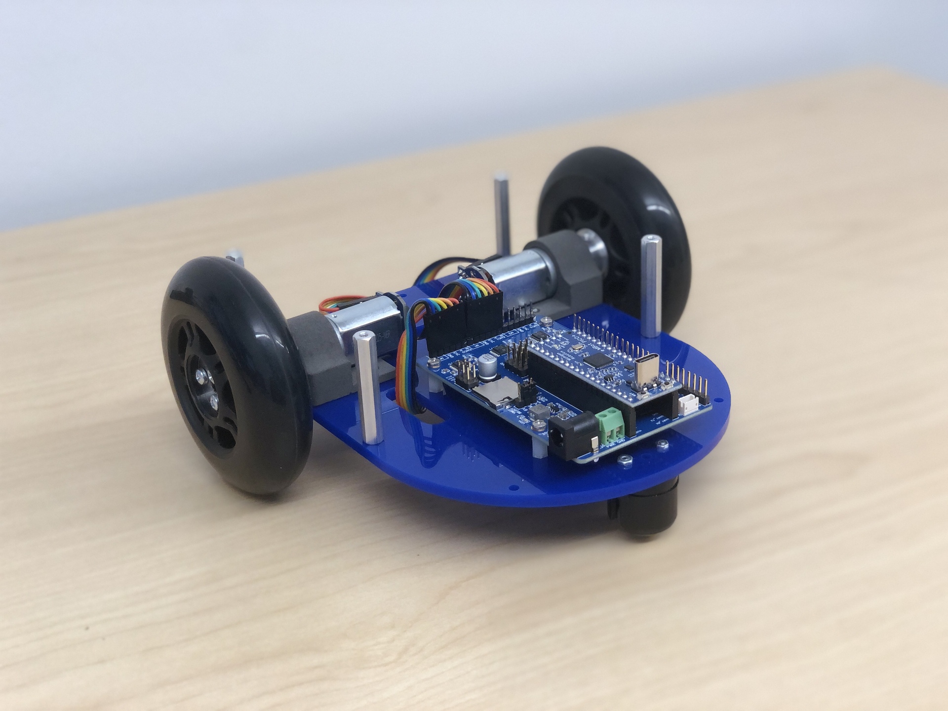
Now you can move to the middle part!