Hardware
Last Updated: Sep 02, 2026
What is at your station: the arm, the gripper, the camera, and how it is all powered and connected.
Contents
- Contents
- Station Overview
- UFactory Lite 6 Arm
- Gripper / End Effector
- Power and Network
- RealSense Camera
- Board and Workspace
- Reference Links
Station Overview
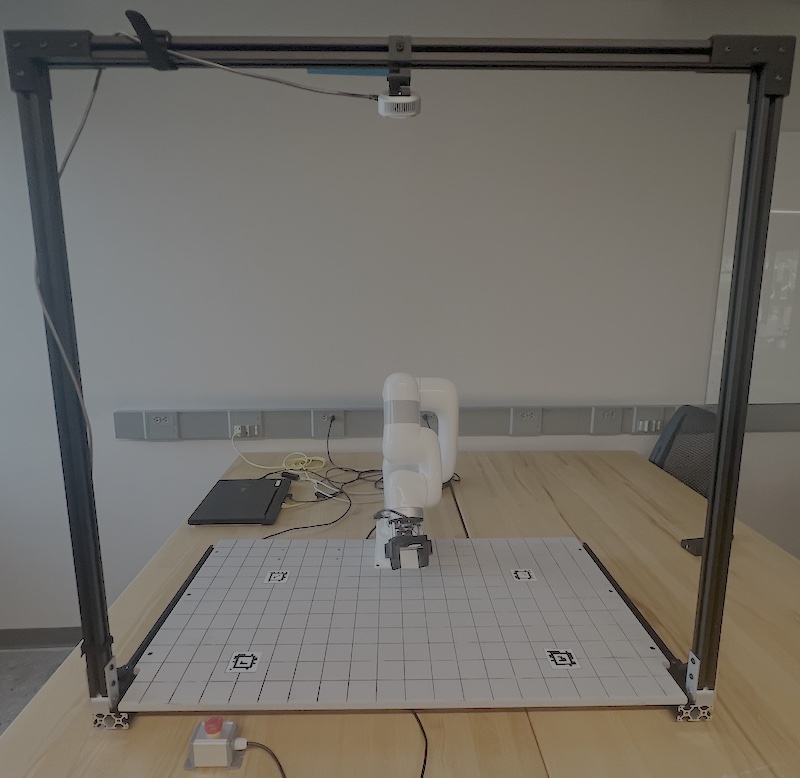
Every station has the same parts:
- the Lite 6 arm, bolted to the back edge of the board
- the board, marked with a 50 mm grid and carrying an AprilTag near each corner
- the aluminum frame spanning the table, with the RealSense camera mounted on the top rail looking down
- the 24 V power supply, under the board
- the laptop, running the control station
- the emergency stop, loose on the table beside the arm, the red button in the foreground above
UFactory Lite 6 Arm
The arm is a UFACTORY Lite 6, a 6-DOF collaborative arm with the control electronics built into its base, so there is no separate controller cabinet. It is commanded over Ethernet from the station laptop using the xArm Python SDK.
| Specification | Value |
|---|---|
| Degrees of freedom | 6 |
| Reach | 440 mm |
| Payload | 600 g |
| Repeatability | ±0.5 mm |
| Weight | 7.2 kg |
| Max TCP speed | 500 mm/s |
| Max joint speed | 180 °/s |
| Power | 24 V DC |
| Communication | Ethernet |
| Tool flange | ISO 9409-1-50 |
Joints
The six joints are numbered from the base outwards. You will see these numbers in the web interface, in the control station readouts, and in every error message the arm produces.
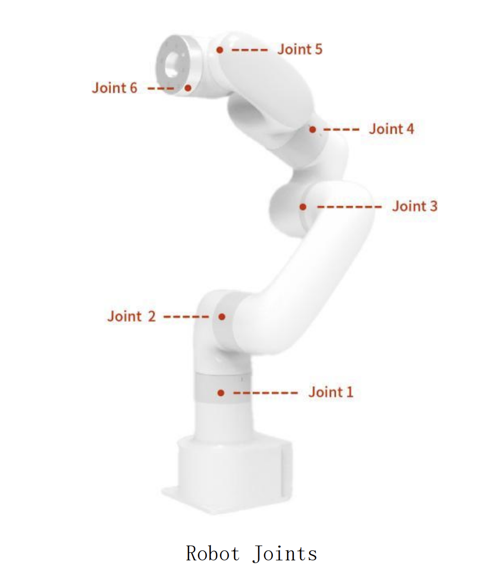
Each joint also has a sign convention, which way counts as a positive angle:
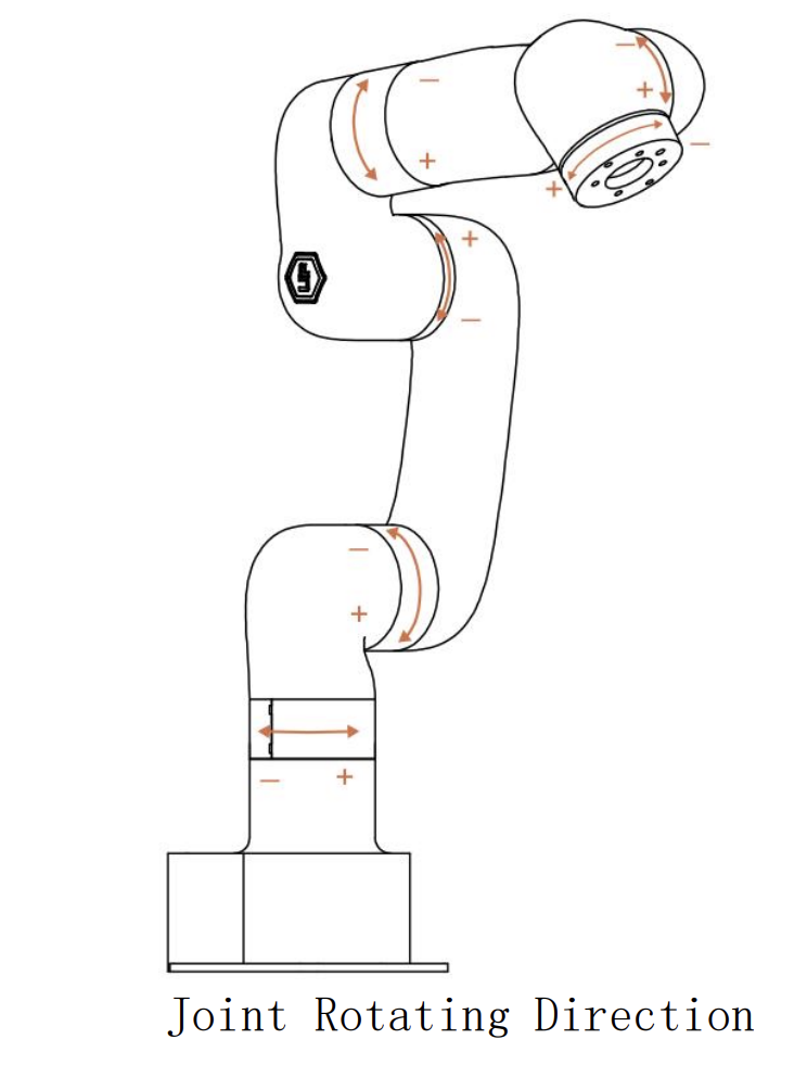
Check a joint’s sign here before you assume your math is wrong. A forward-kinematics result that is right in magnitude but wrong in sign is usually a joint turning the opposite way to what you assumed.
Joint travel limits are not symmetric:
| Joint | Range |
|---|---|
| J1 | ±360° |
| J2 | ±150° |
| J3 | −3.5° to 300° |
| J4 | ±360° |
| J5 | ±124° |
| J6 | ±360° |
J5 (±124°) and J3 (−3.5° to 300°) are the limits you will actually run into. An inverse-kinematics solution can be mathematically correct and still unreachable because it asks one of these joints to go somewhere it cannot. See the Lite 6 Arm & SDK Guide for how this shows up in the software.
The 600 g payload includes whatever is bolted to the flange, but the gripper is only about 50 g, so roughly 550 g is left for the object. The wooden blocks used in this lab weigh a small fraction of that, so payload is not a constraint you will run into here.
Zero position
At the zero configuration, with all six joint angles at 0, the arm stands straight up, and the tool flange sits 87 mm out in x and 154.2 mm up in z from the base frame origin.
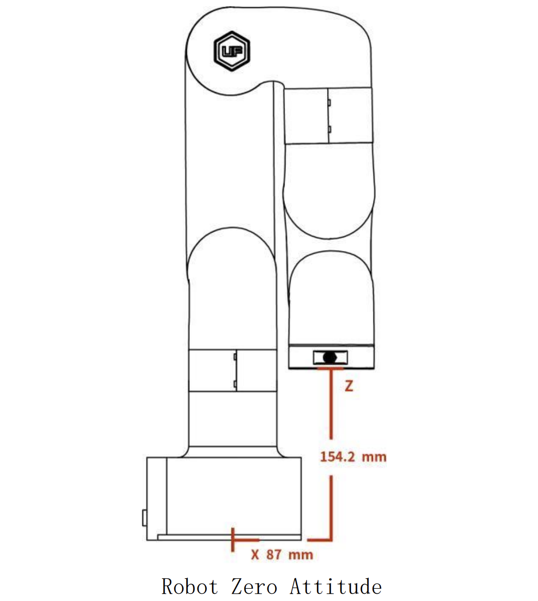
These two numbers are a free check on your forward kinematics. Feed your FK all zeros and it should put the flange at (87, 0, 154.2) mm. If it does not, the error is in your DH table or your zero offsets, and it is much easier to find here than anywhere else.
The arm is otherwise unmodified for this course. The only change is the custom gripper on the tool flange.
The emergency stop is on the table next to the arm. Find it before you power the arm on. Safety rules for the lab will be covered by the staff in person.
Gripper / End Effector
The gripper is custom-built for this lab, mounted on the Lite 6’s ISO 9409-1-50 tool flange. It is commanded with the standard Lite 6 gripper calls: open_lite6_gripper(), close_lite6_gripper() and stop_lite6_gripper(); see the Lite 6 Arm & SDK Guide.
It is a binary open/closed device: no width control, no force control, and no feedback about whether a grasp succeeded.
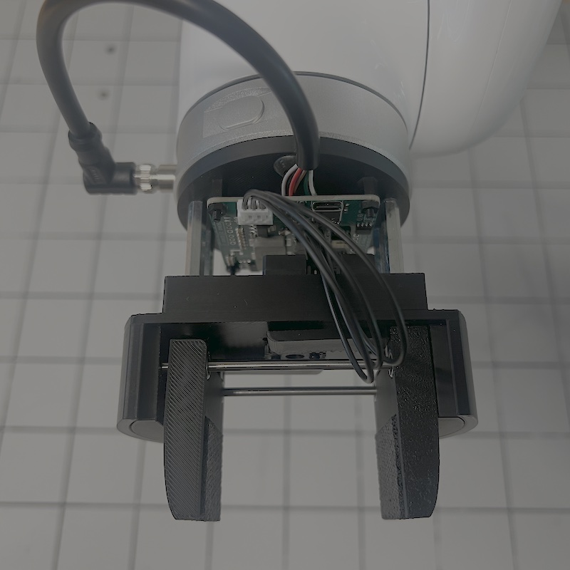
It is a parallel-jaw design: two flat fingers that travel together, driven by the board visible behind them.
| Property | Value |
|---|---|
| Grasp stroke | 50 mm |
| Overall length | 100 mm |
| Mass | ~50 g |
| Flange to finger center | 85 mm |
The 85 mm offset is the number your kinematics needs. Forward kinematics gives you the pose of the tool flange; the point that actually grasps a block sits 85 mm further along the tool axis. Leave it out and every pick will aim 85 mm short.
The gripper hangs 100 mm below the flange. Coming down on a block from above, the flange has to stay more than 100 mm above the board or the fingertips reach it first. The readout and your FK both report the flange, so that clearance is yours to keep track of.
A 50 mm stroke sets the ceiling on what you can pick up, and the board’s grid squares are 50 mm, which makes them a convenient check on whether a block will fit in the jaws.
Power and Network
The Lite 6 has no separate controller cabinet. The control electronics are inside the arm’s base. Power comes from a 24 V power supply mounted underneath the board the arm is bolted to.
The arm talks to the station laptop over Ethernet, through a USB-to-Ethernet adapter. That adapter is what gives the laptop a second Ethernet port.
| Item | How it connects |
|---|---|
| Arm power | 24 V supply mounted under the board |
| Arm data | Ethernet → USB-to-Ethernet adapter on the laptop |
| Internet | The laptop’s built-in Ethernet port |
| Camera | USB 3.x to the laptop |
Do not plug the arm into the laptop’s built-in Ethernet port. That port is reserved for internet access and sits on a different IP address and subnet. The arm must go through the USB-to-Ethernet adapter, or it will not be reachable.
Each arm has its own IP address, printed on a label on the back of the arm. You set it in the code during setup.
RealSense Camera
Perception uses an Intel RealSense LiDAR Camera L515. Unlike the stereo RealSense models, the L515 measures depth with a solid-state MEMS LiDAR, which gives it a clean, low-noise depth image at close range, well suited to looking down at blocks on a board.
| Specification | Value |
|---|---|
| Depth technology | Solid-state MEMS LiDAR |
| Operating range | 0.25 – 9 m |
| Depth field of view | 70° × 55° |
| Depth stream used in this lab | 1024 × 768 @ 30 fps |
| Color stream used in this lab | 1280 × 720 @ 30 fps |
| Depth accuracy | ~5 mm at 1 m |
| Connection | USB 3.x (Type-C) |
| Size | 61 mm diameter × 26 mm |
The depth and color streams come from two physically separate sensors, so camera.py aligns depth to color before anything else. After alignment a pixel (u, v) means the same point in both images.
USB 3.x is required. On a USB 2 port the full-resolution profiles are unavailable and the camera will not stream at the settings the control station asks for. Check the connection type with rs-enumerate-devices -s.
The L515 is an indoor sensor: its LiDAR competes with ambient infrared, so strong sunlight degrades the depth image. It is also discontinued by Intel, which is why the lab pins librealsense to 2.54.2, the last version that supports it.
The camera runs in the Short Range visual preset. Without it the firmware discards depth closer than about 411 mm, which would blank out the near part of the workspace.
See the Camera Guide for the RealSense Viewer and calibration.
The camera is mounted on an aluminum frame above the arm, looking down at the board. Its aim is adjustable: loosen the screw with a hex key, rotate the camera to where you want it, then tighten the screw again.
Aiming the camera invalidates your extrinsic calibration. The calibration solves for where the camera sits relative to the robot, so any time you loosen that screw you have to run Calibrate again before world coordinates mean anything.
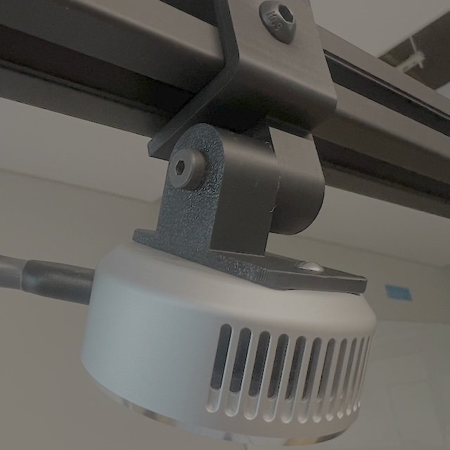
The hex screw in the bracket is the one to loosen when you re-aim the camera. The camera sits roughly 1 m above the board.
That 1 m working distance is where the L515’s quoted ~5 mm depth accuracy applies, and it is comfortably inside the sensor’s 0.25–9 m range.
Board and Workspace
The arm is mounted on a board carrying AprilTags at fixed positions.
Measure the board yourself. You need the grid spacing, the position of the robot frame origin, the direction of its axes, and the location of each tag relative to that origin. Those measured tag positions are exactly what goes into TAG_WORLD_POINTS in camera.py. Your extrinsic calibration can be no better than these measurements, so take them carefully and record them in your report.