mbot_xl320_lib Guide
Last Updated: Nov 18, 2025
This guide introduces how to program the XL320 servo using the
mbot_xl320_librarycode example provided.
Contents
Assembly
We use the custom UART to XL320 board here:
| Components | Number |
|---|---|
| Connector Housing (looks like this) - 6 pin | 1 |
| Connector Housing (looks like this) - 3 pin | 1 |
| Connector Housing (looks like this) - 2 pin | 1 |
| Connector Housing (looks like this) - 1 pin | 1 |
| UART to XL320 board | 1 |
| XL320 servo | based on your project |
| Jumper wires (Black/Red/Yellow/Blue/Green/White) | 6 |
0. Get all the components
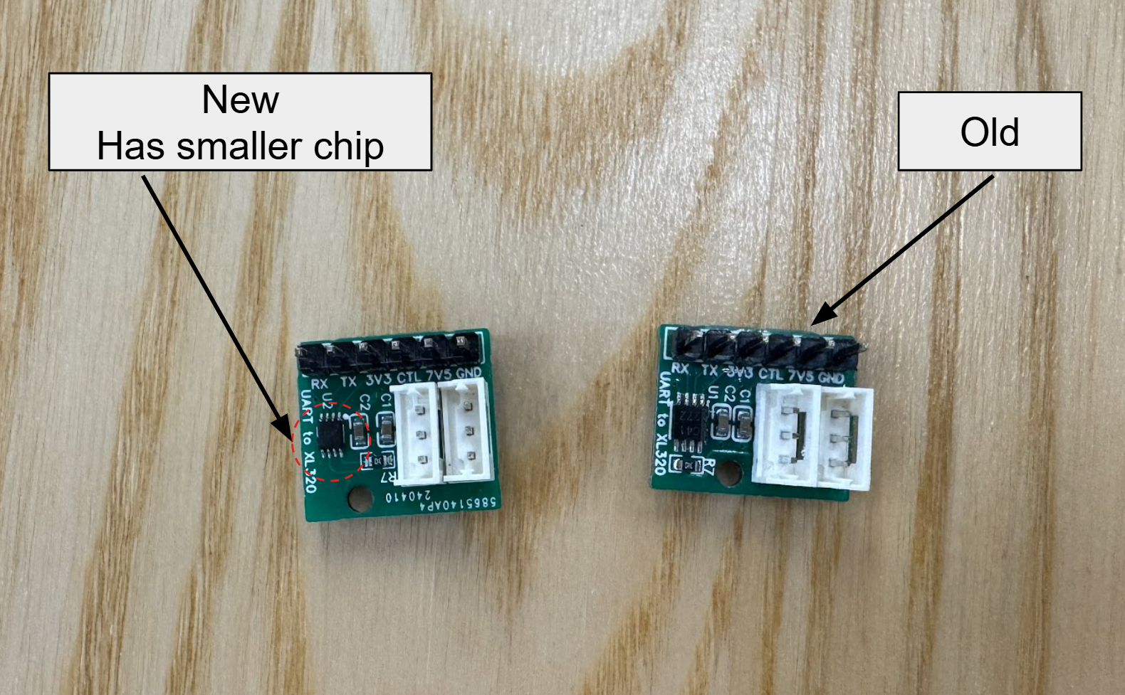
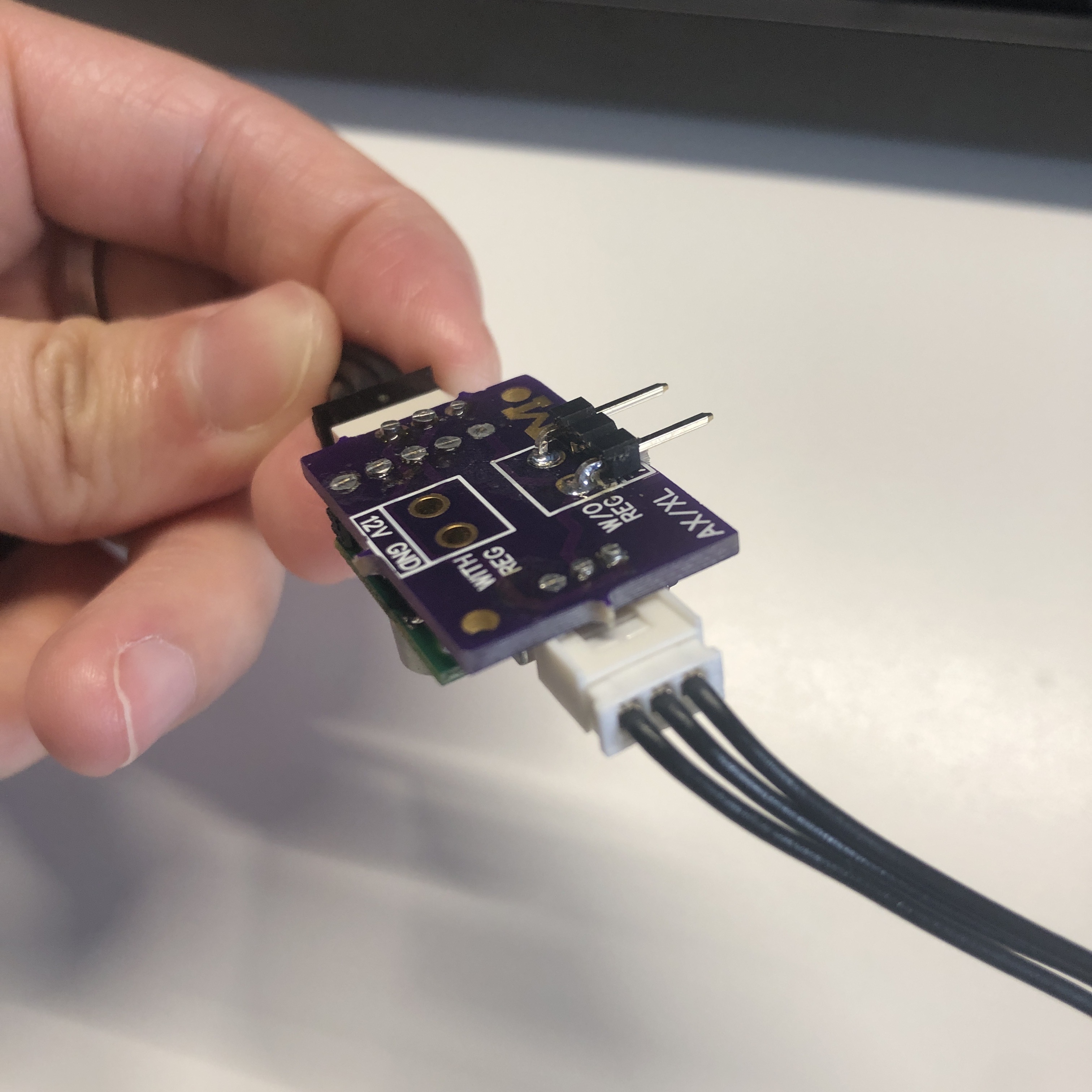
One thing to notice, there are 2 versions of UART to XL320 boards, show in the image below. Always choose the newer version:
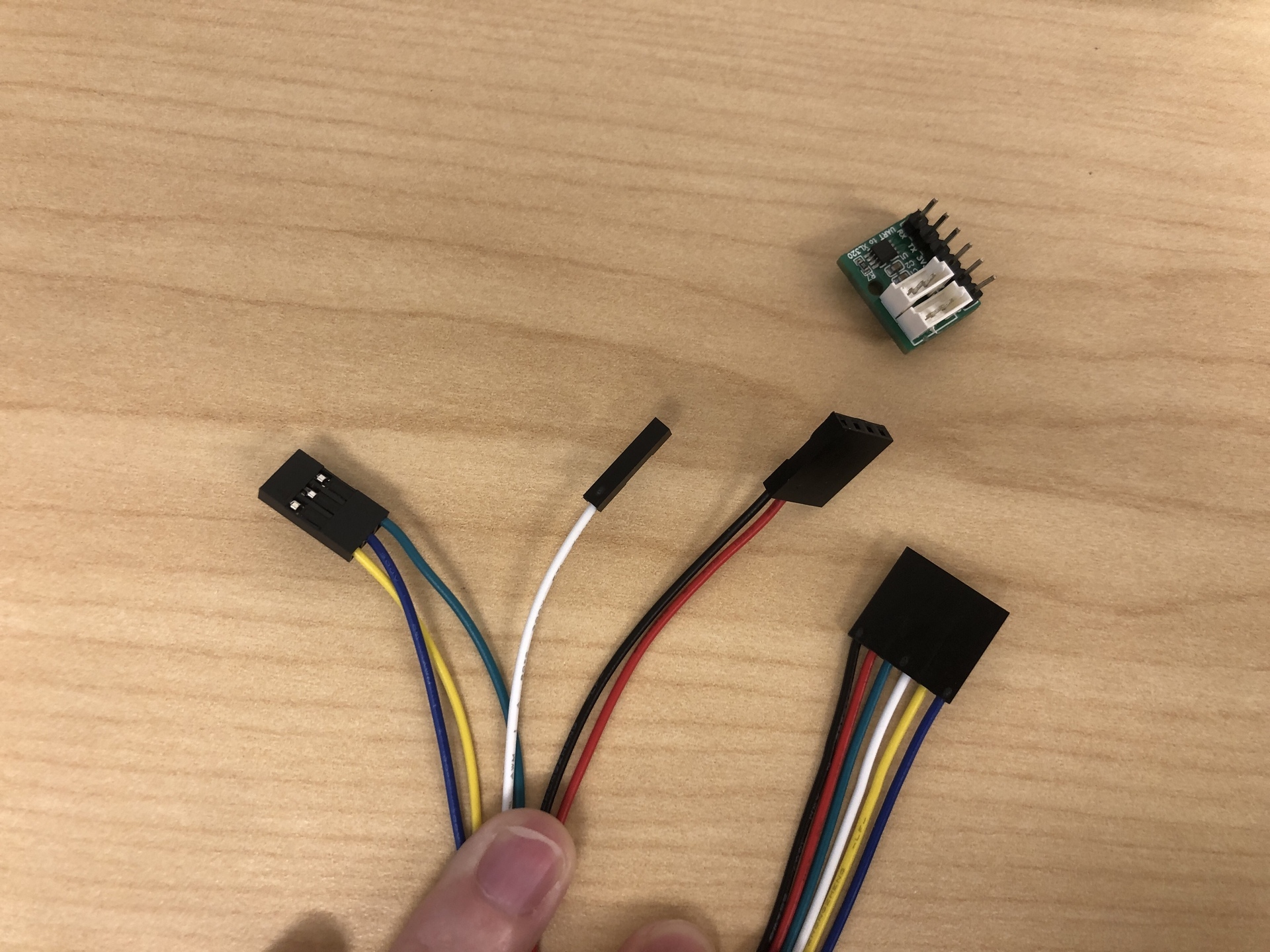
1. Assemble the jumper wires with the connector housings:
- 6-Pin housing: Insert the wires in the following order: black, red, green, white, yellow, blue.
- Refer to the image below. This color order is not mandatory if you are familiar with circuit wiring, but maintaining consistency across all setups in the class simplifies troubleshooting later.
- 3-Pin housing: Insert the wires in the order of yellow, blue, green.
- 2-Pin housing: Connect the black and red wires.
- For this one, you can use any of 2-pin, 3-pin, or 4-pin housing, just remember to put black on the side, and red wire next to it. This will later connect to the servo pin header on the control board. The header itself has four pins arranged together, so any of these housing options (2/3/4 pin) will fit and function correctly.
-
1-Pin housing: Connect the white wire.
2. Connect UART board, Pi 5, and Control board
| Wire | Pin | Info |
|---|---|---|
| Blue | RX (Receive) | where Pi 5 listens for signals |
| Yellow | TX (Transmit) | where Pi 5 sends out signals |
| White | 3V3 | power the logic circuit |
| Green | CTL (Control) | this pin acts like a switch |
| Red | 7V5 | power the servo |
| Black | GND |
The table above outlines the relationship between colors and pins.
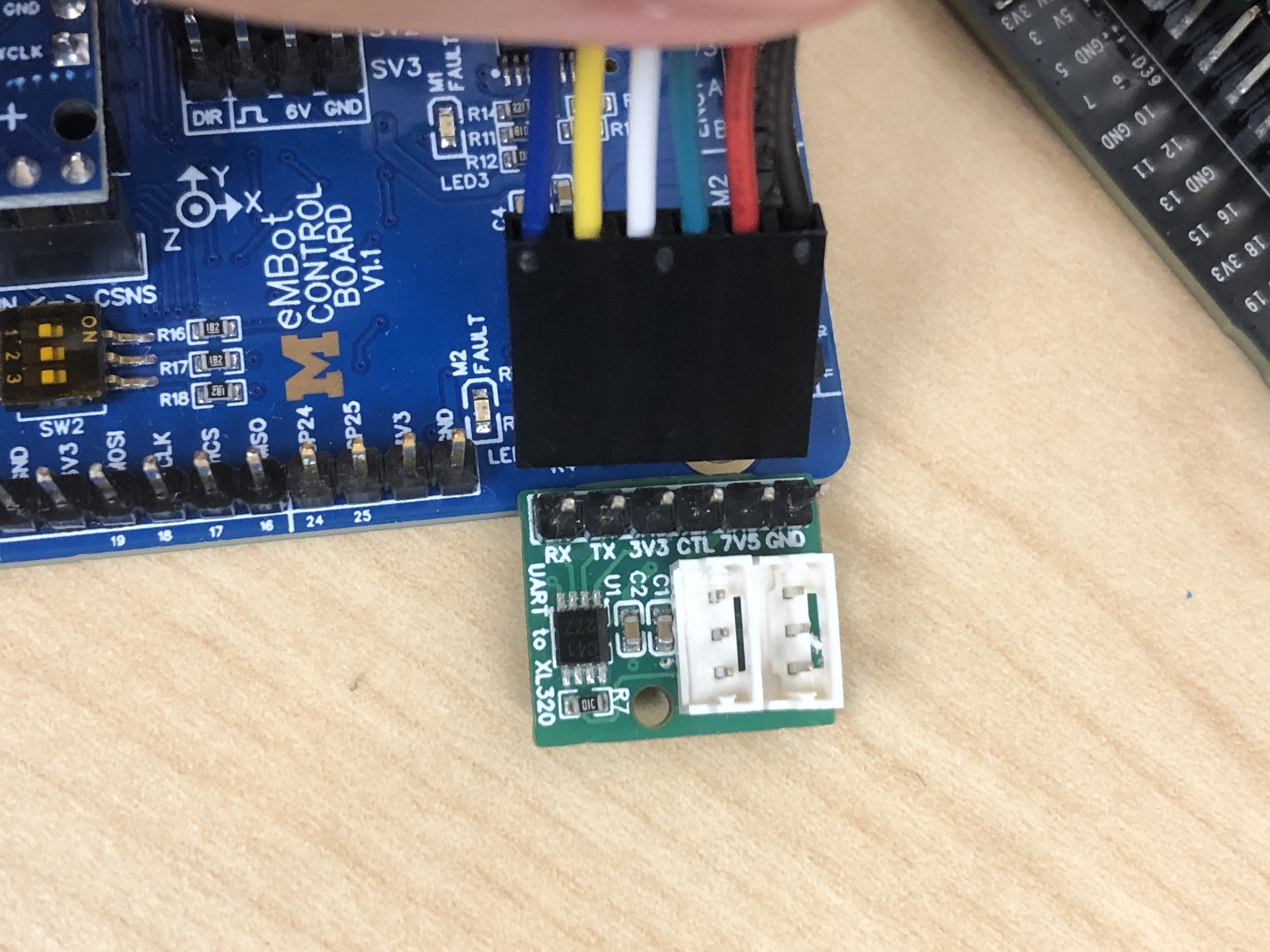
- Refer to the first image below to connect the 6-pin connector to the UART board.
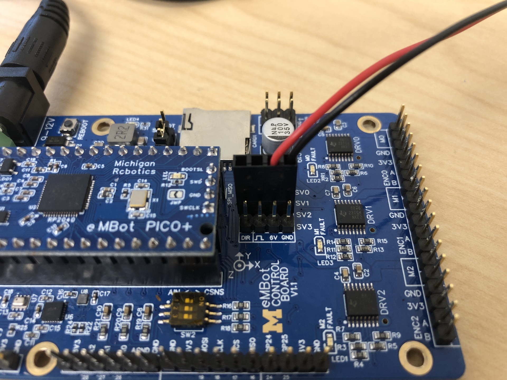
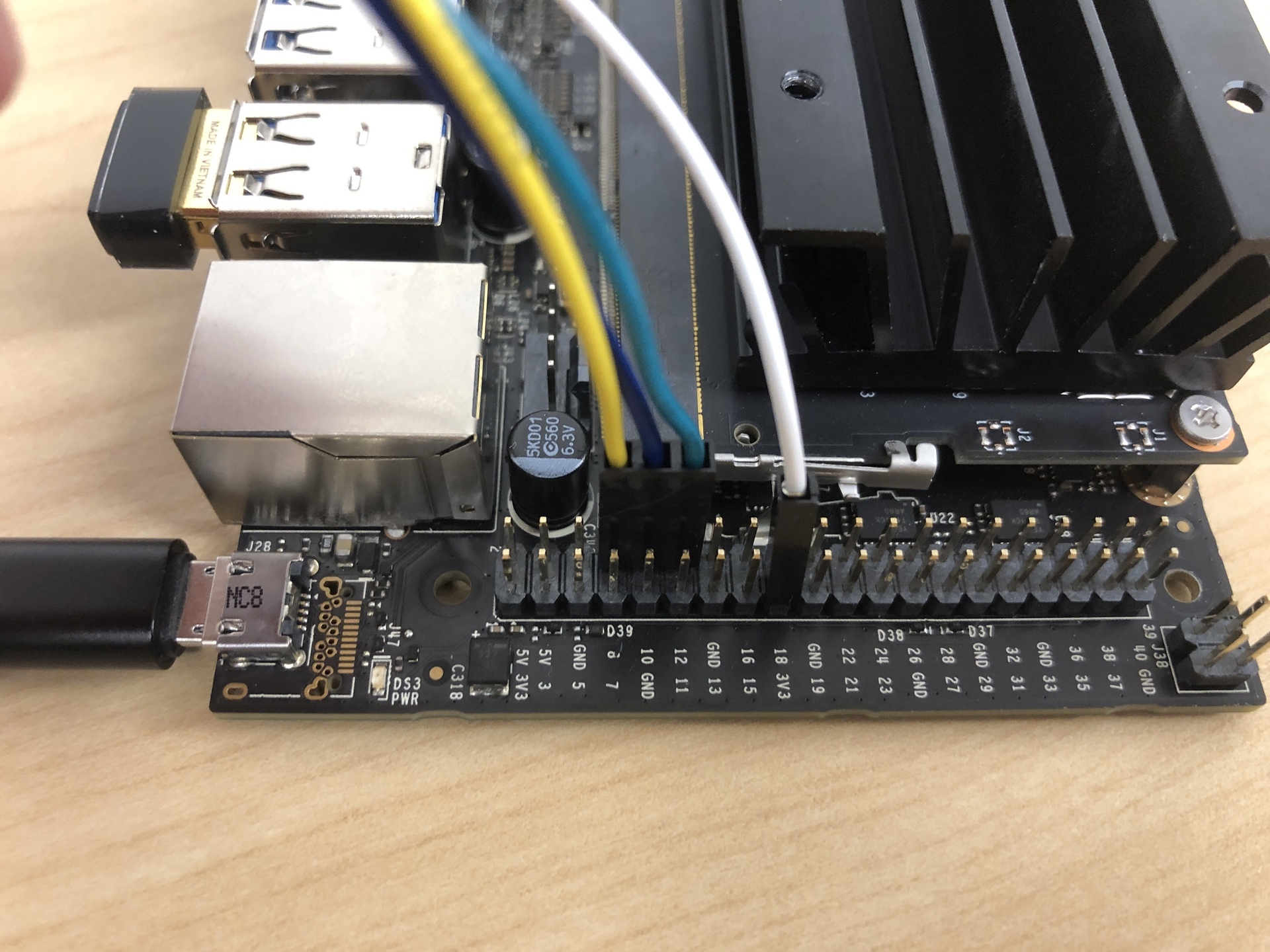
- The second image, attach the 2-pin connector to the control board. You can choose any of the
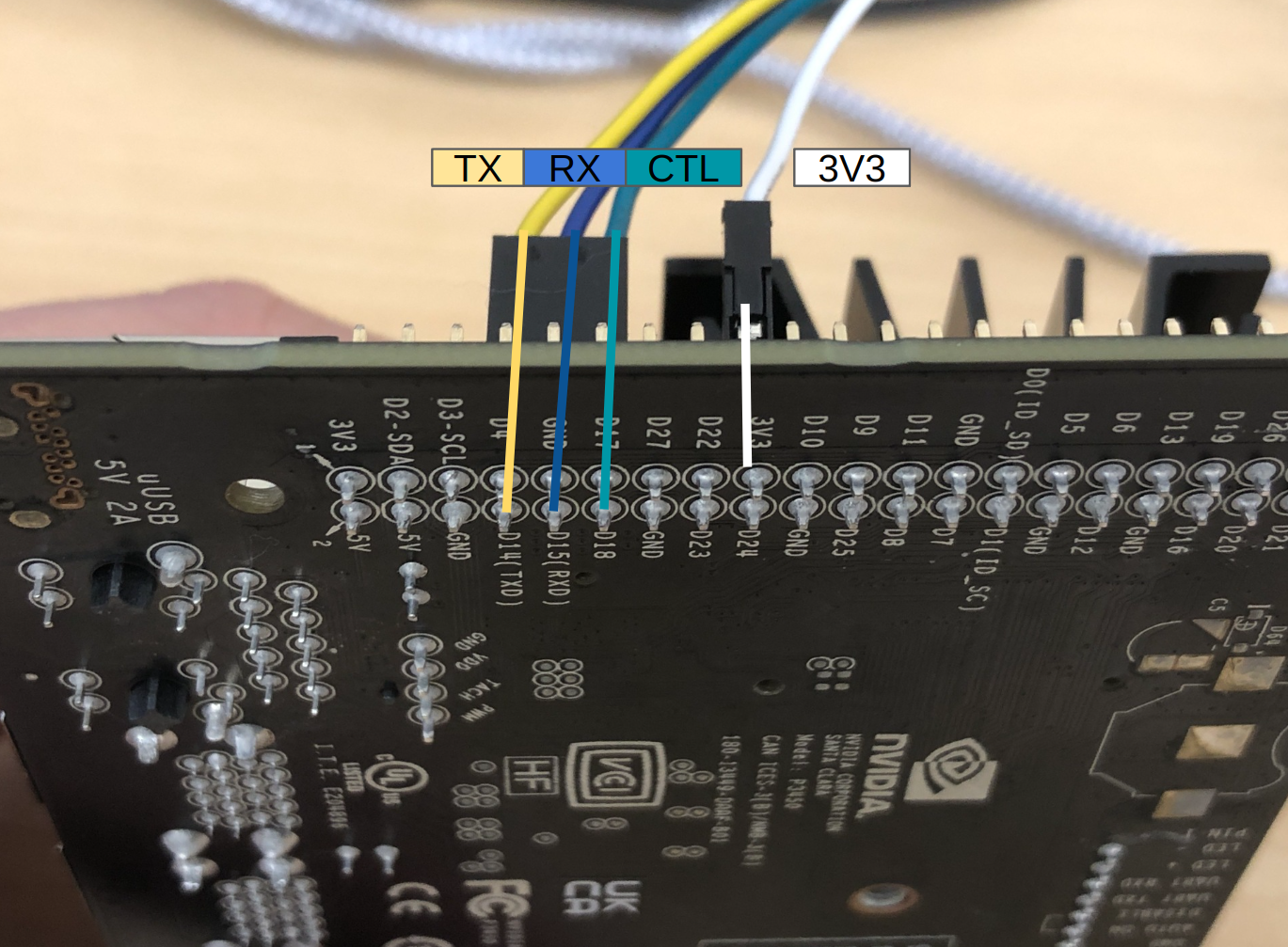
SVslots. Red to 6V, black to GND. - The third image, show where to connect the 3-pin to the Pi 5.
- The fourth image, show where to connect th 1-pin connector, PIN 17 (3V3 Power)
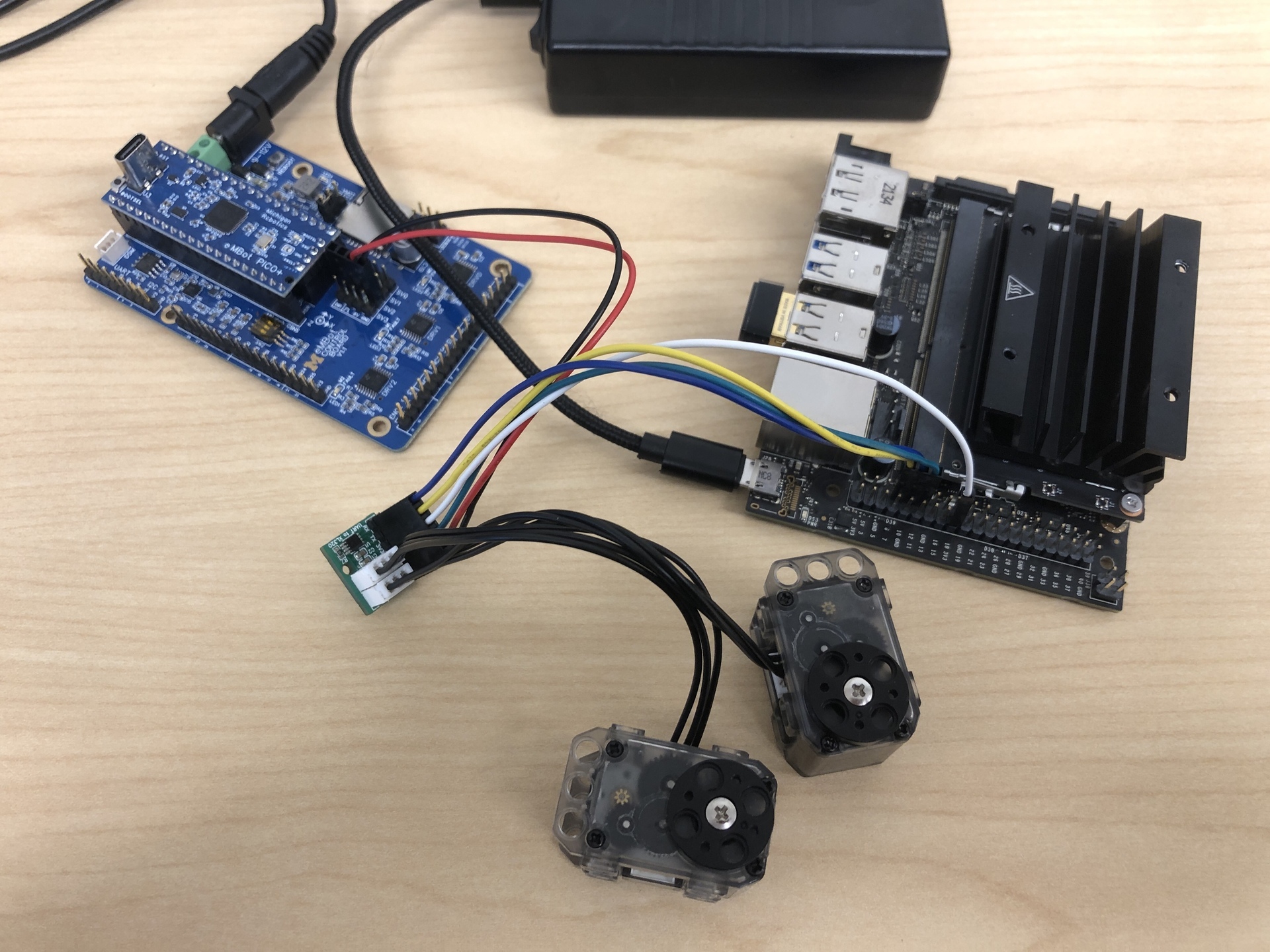
3. Connect the 2 servos to the UART board
The result should look like the image below:
System setup
- Edit the Configuration File.
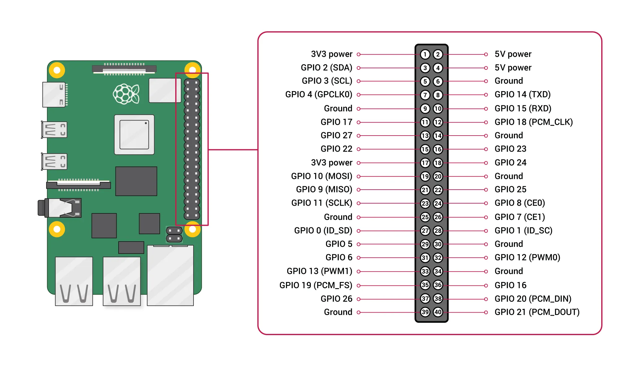
sudo nano /boot/firmware/config.txt - Add UART Overlay: Add the following lines to the end of the file to enable the primary UART on GPIO pins 14 (TX) and 15 (RX) :
[pi5] dtoverlay=uart0-pi5 - Reboot the Pi: Save the file and reboot your Raspberry Pi for the changes to take effect.
sudo reboot - Test. Run the following command we should see
ttyAMA0listed.$ ls /dev | grep ttyAMA ttyAMA0 ttyAMA10 - Run the following to add user to
dialoutgroup:sudo usermod -a -G dialout $USER- Test, run
groupsand you should seedialoutlisted.
- Test, run
Install
Run the following commands to install the XL320 library
cd ~
git clone https://gitlab.eecs.umich.edu/rob550-f25/mbot_xl320_library
cd ~/mbot_xl320_library
./install.sh
How to use
- Check the servo ID. This program will ping all the possible IDs and give you the list of connected ID.
cd ~/mbot_xl320_library/tests python3 check_servo_id.py- Check the ID output. If you have two or more servos connected but the program detects none, or doesn’t list all of them, it likely means:
- either one of the servos is broken
- or multiple DYNAMIXELs share the same ID.
- It is recommended to connect only one servo at a time to check its ID and change it if you find duplicates.
- Check the ID output. If you have two or more servos connected but the program detects none, or doesn’t list all of them, it likely means:
- If there are duplicate IDs, connect only one of the affected servos to the board (no other servos should be connected), then modify
change_servo_id.pyto assign it a new ID.CURRENT_ID = 1 # The ID you want to change NEW_ID = 3 # The new ID you want to setThen run:
python3 change_servo_id.py - We have 2 exmaples
tests/rotate_full_range.pyandtests/rotate_in_circle.py. You need to define the servo ID to use the 2 examples, and the IDs are the ones you obtain from the step 1.# defines the servo's ID servo1_ID = 1 servo2_ID = 2Then run:
python3 rotate_in_circle.py
Uninstall
sudo pip3 uninstall dynamixel_sdk mbot_xl320_library --break-system-packages
After uninstalling, if you want to remove the folder, run:
sudo rm -rf mbot_xl320_library
- Please DO NOT uninstall it directly by
sudo rm -rf mbot_xl320_library, this will cause error when you re-install it.
Troubleshooting
If you have errors saying:
"[RxPacketError] Hardware error occurred. Check the error at Control Table (Hardware Error Status)!"
"[TxRxResult] There is no status packet!"
There could be many reasons behind this issue. If everything still functions but you continue to see these errors, try unplugging and then replugging the wires to ensure all connections are secure.
Legacy
This is irrelavant to 2025 ROS2 MBot!!!
0. Using USB to TTL adapter and AX to XL320 adapter
- To prepare your adapter board for connection, you need to solder a 3-pin right-angle header onto the board, and snip the middle pin. Refer to the first image below for details.
- Once the header is in place, proceed to connect all the components as illustrated in the second image.
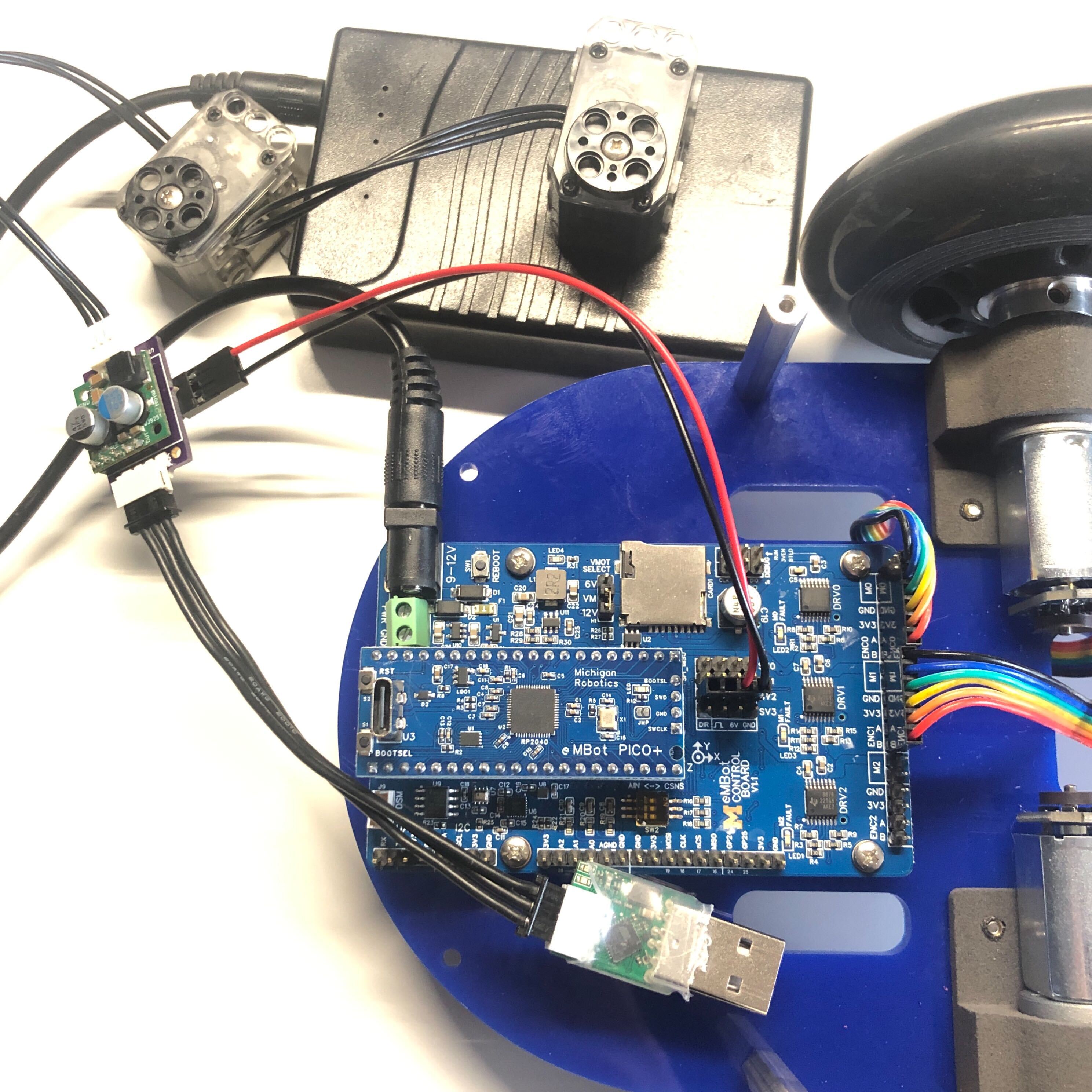
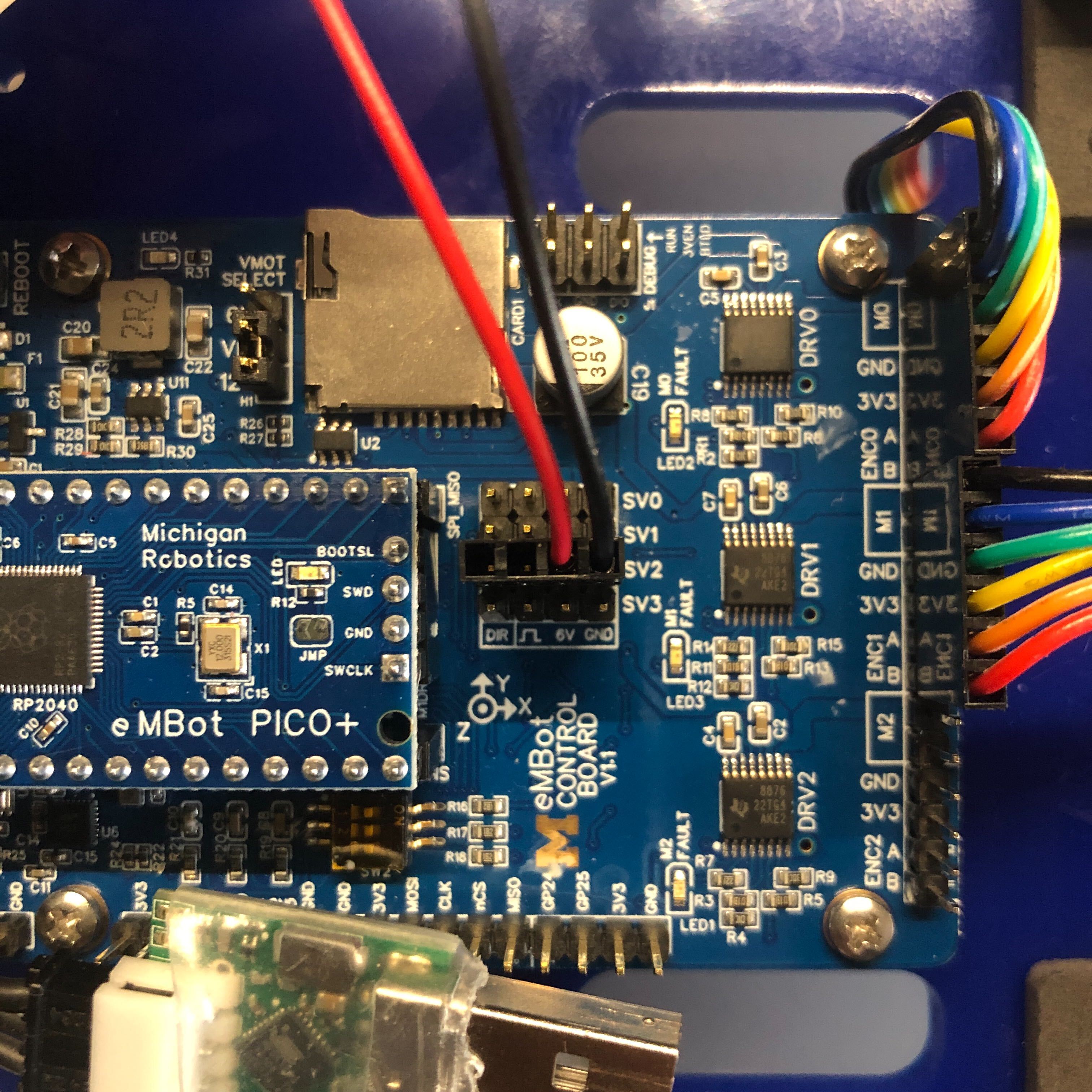
- Next, attach the power cable to the control board as shown in the third image. We use the power bank to power the control board, and use the servo port to power the two XL320 servos. For clarity, see the fourth image. Note that we are using the SV2 port, make sure to connect the GND pin and the 6V pin accordingly on both ends.

1. Download “Dynamixel Wizard 2.0”
Using Dynamixel Wizard, you can change the servo’s ID, check the port name, and make many other adjustments.
- Download Dynamixel Wizard 2.0 onto your laptop, or use the lab’s laptop that already has “Dynamixel Wizard” installed.
- Then plug the USB into the laptop and open the Dynamixel Wizard.
- Click “Scan”: the application will begin scanning for any connected servos. This process may take some time.
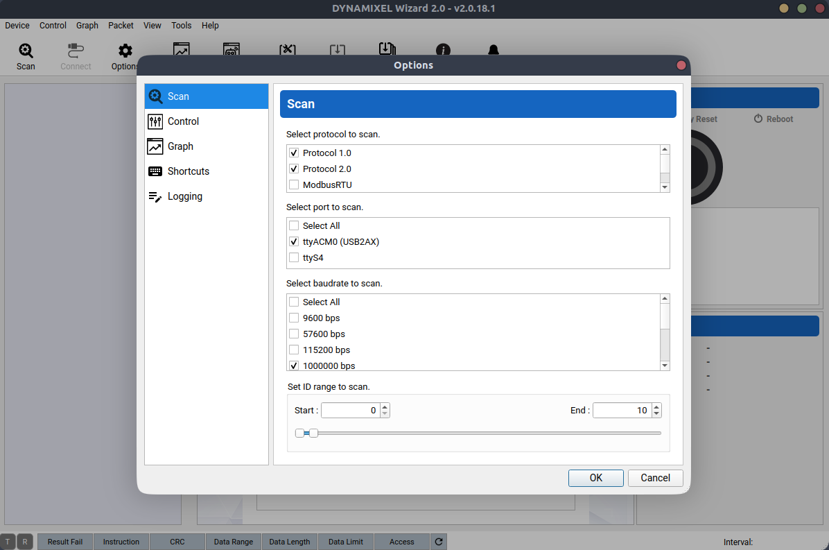
- Click “Options”: a window will appear as shown below, where you can deselect some options to speed up the scanning process. For instance, you can narrow the ID range, choose the default baud rate, and select only Protocol 2.0 since the XL320 uses Protocol 2.0.
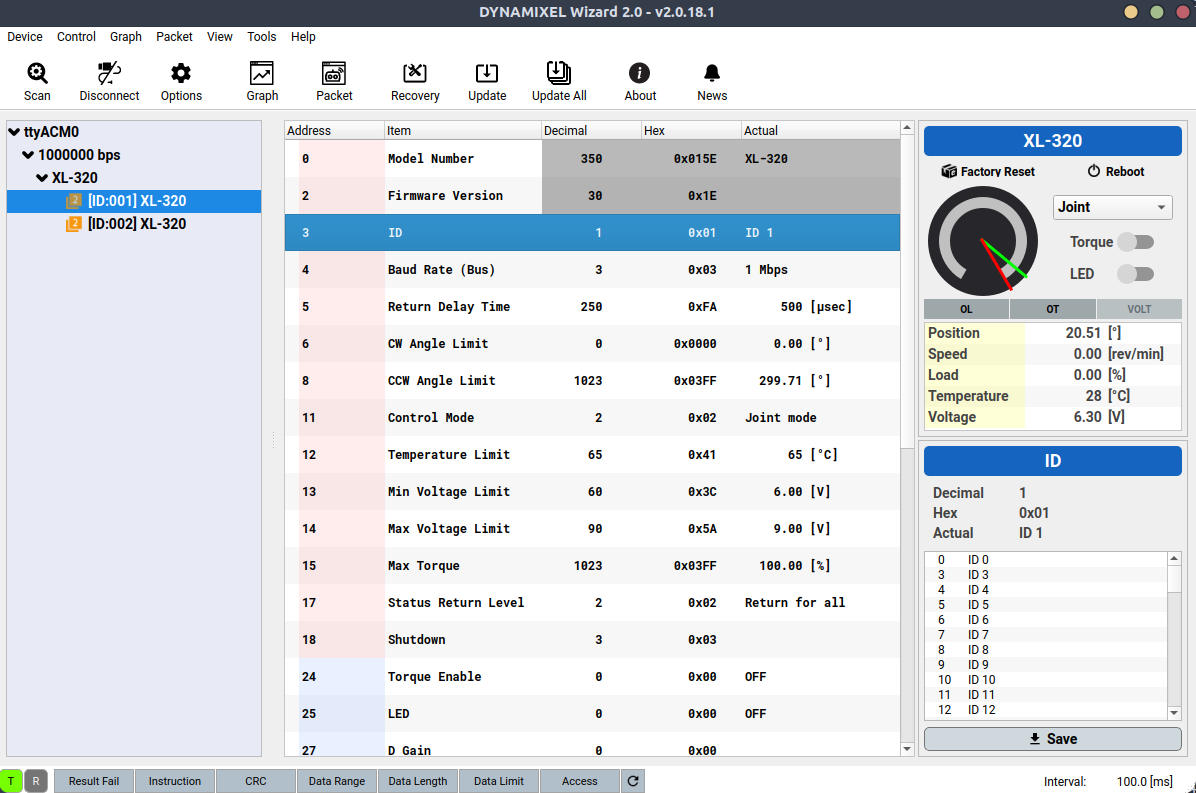
2. Check your servo’s ID
You will need to specify your servo’s ID when using the XL320 library we provide. To check your servo’s current ID or change it to your preferred number, you need to use the Dynamixel Wizard.
In the image below, you will notice that there are two servos: one with ID 1 and the other with ID 2. To change these IDs, click on the corresponding servo, and in the right-side panel select your preferred ID, and then click “Save” to apply the new ID.
If you’re unsure which servo is which, you can identify each one by toggling the LED switch on and off. This will allow you to visually confirm which servo you are configuring.
After successfully confirming your servo’s ID, we no longer need Dynamixel Wizard. Disconnect the USB from the laptop and connect it to the Pi.
3. Check the port name
-
Option 1: Using command line tool
dmesgWhen plugged the USB into the Pi and using VSCode’s remote, you can use the command line tool to check:
sudo dmesg | grep ttyThis command shows kernel messages related to tty devices and filters the output for the string “tty”. Look for lines that mention a new device being attached. The device will usually be listed as
/dev/ttyUSB0,/dev/ttyACM0, or similar.For instance, the output might include a line similar to:
[ 8263.926975] cdc_acm 1-9:1.0: ttyACM0: USB ACM deviceHere, the port name is
/dev/ttyACM0 -
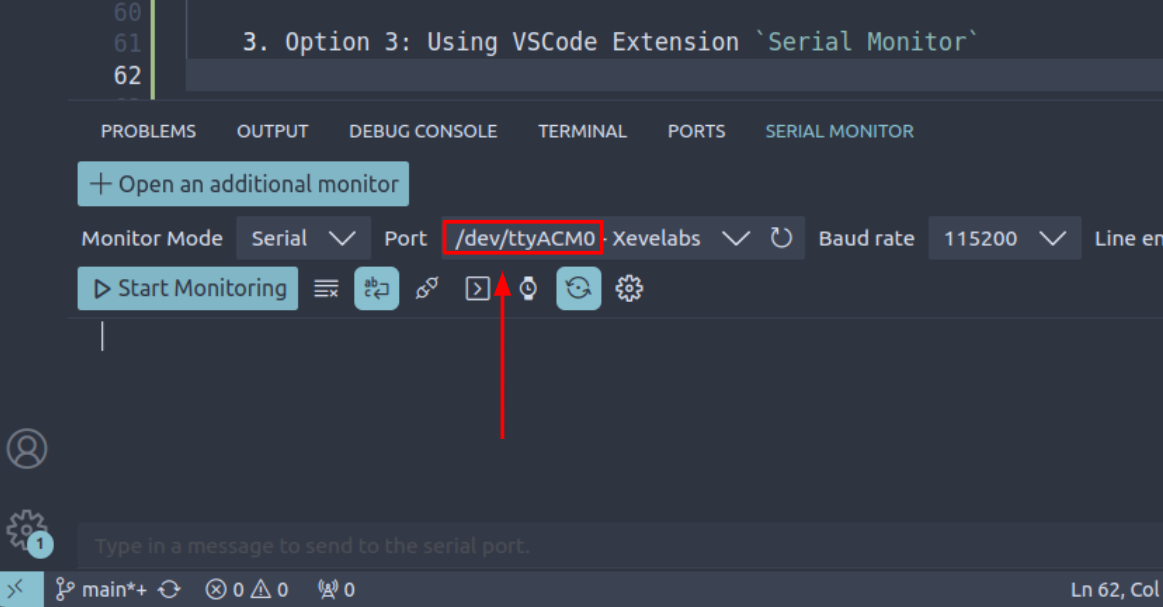
Option 2: Using VSCode Extension “Serial Monitor”
Download the VSCode Extension “Serial Montior”, then open the panel by clicking Terminal -> New Terminal. You should see you have a new tab: Serial Monitor, where you can check detected port name there.
To run the examples, you need to modify some of the variables to suit your specific setup:
CONNECTION_DEVICE = "UART" # change to "UART" if you are using UART connection
#CONNECTION_DEVICE = "USB" # change to "USB" if you are using USB2AX connection
PORT_NAME = "/dev/ttyACM0" # UART has fixed port name on Pi, no need to check the name
#PORT_NAME = "/dev/ttyACM0" # USB port names are dynamic you need to check what it is
#...
# defines the servo's ID
servo1_ID = 1
servo2_ID = 2