Checkpoint 1
Last Updated: Mar 17, 2026
Contents
- Contents
- Task 1.1 Wheel Calibration
- Task 1.2 PID Tuning
- Task 1.3 Improve firmware
- Task 1.4 Motion Controller
- Checkpoint Submission
Task 1.1 Wheel Calibration
The calibration program checks the polarity of the encoders and motors, then performs a wheel speed calibration. The resulting data are printed to the terminal and stored in the MBot’s non-volatile memory.
The calibration data consists of:
- Encoder Polarity: Defines whether the encoder count increases or decreases relative to the motor’s rotation.
- Motor Polarity: Defines the wheel rotation direction when a positive command is received; the firmware uses this to ensure the wheels spin the correct way.
- Slopes and Intercepts: Define the linear relationship between the PWM duty cycles and the actual speeds of the wheels.
TODO
Open one terminal with Minicom to monitor the calibration output, and use another terminal to flash the calibration firmware to the Pico. Run the calibration several times and collect the resulting data for analysis.
# terminal 1
sudo minicom -D /dev/mbot_debug -b 115200
# terminal 2
cd ~/mbot_firmware_ros/build
sudo mbot-upload-firmware flash mbot_calibrate_classic.uf2
To quit minicom, first press CTRL + A, then press X, then press Enter to quit. Alternatively, you can simply close the terminal window.
Tips:
- Close your current Minicom session before starting a new one (prevents port errors).
- Stay organized: Don’t hoard terminal windows. Keep only what you need open so you don’t get confused.
Once you’ve finished collecting data, remember to flash the firmware back to the control board.
cd ~/mbot_firmware_ros/build
sudo mbot-upload-firmware flash mbot_classic_ros.uf2
Perform the calibration on each robot in your group at least 5 times, report the motor calibration with variance for the robot on a concrete floor (like in the lab).
Questions to Consider:
1) How much variation is there in the calibration for a single robot? Between the team robots?
2) What do you think is the source of variation?
Task 1.2 PID Tuning
There are 3 drive modes and 3 control modes in firmware source code.
Drive Modes
- PWM Control — You directly send PWM commands to individual motors.
- Wheel Velocity Control — You send wheel velocity commands to individual wheels.
- Robot Velocity Control — You send robot body velocity commands
vxandwz.
Control Modes
- Feedforward (FF) Control Only
- PID Control Only
- Feedforward + PID Control
The drive mode is automatically selected based on the type of control command you send:
- If you publish to
/cmd_vel, Robot Velocity Control mode will be selected, meaning the robot will interpret commands as body velocities.
The control mode is automatically selected when you flash the calibration script. The default mode is Feedforward Control Only. During calibration, the script reads the default parameters from mbot_firmware_ros/include/config/mbot_classic_default_pid.h and writes them to FRAM.
You can tune the PID gains at runtime via the ROS parameter server.
You may notice that only wheel-level PID gains are exposed. This is because Robot Velocity Control is implemented on top of Wheel Velocity Control:
- The commanded body velocities (vx, wz) are first converted into individual wheel velocities using the robot kinematics.
- These wheel velocity commands are then tracked using the selected control mode (FF, PID, or FF+PID), which ultimately generates PWM commands for the motors.
TODO
Tune the PID values to achieve a desired system response.
How to tune?
- First, modify the values in
~/mbot_firmware_ros/include/config/mbot_classic_pid.yaml. You can tune the PID gains for both wheels, and select control modes there. - After modifying the values in the yaml file, run the command below to load the new configs:
cd ~/mbot_firmware_ros ros2 param load /mbot_control_node include/config/mbot_classic_pid.yaml - If you want to check whether the values are actually loaded, run:
ros2 param dump /mbot_control_node- If you see the values you set, it means the new PID gains have been applied to the MBot and written to the FRAM. You can run test now!
- The PID values will persist after rebooting. However, if you flash the calibration again, the calibration script will overwrite your tuned PID gains by the values in
mbot_firmware_ros/include/config/mbot_classic_default_pid.h, and you’ll need to reload the YAML file to restore them by running the command from step 2.
mbot_firmware_ros/python-tests/step_cmd_test.py: This script sends robot body velocity to drive robot forward, and rotate clockwise then counterclock-wise.cd ~/mbot_firmware_ros/python-tests/ python3 step_cmd_test.py- Running the script above to command the robot, we can then plot commanded velocity versus actual velocity to evaluate tuning performance and further refine your gains. To do this, you can either write a Python script in the
python-testsfolder to log data from thecmd_velandodomROS topics, or use Foxglove for real-time plotting. If you followed the system setup guide, Foxglove should already be installed.- To use foxglove, first always run the foxglove bridge
ros2 launch foxglove_bridge foxglove_bridge_launch.xml - video demo - use foxglove to tune
- To use foxglove, first always run the foxglove bridge
Tip:
- We define robot’s base radius in
~/mbot_firmware_ros/include/config/mbot_classic_config.h.DIFF_BASE_RADIUSvalue (in meter) represents the robot’s base radius. The base diameter is the distance from the center of one wheel to the center of the other. Inaccuracy of this value also affect the robot body velocity, we use this value inmbot_firmware_ros/src/mbot_classic_ros.c. - If you modified
DIFF_BASE_RADIUS, remember to recompile the firmware and flash it to the control board.cd ~/mbot_firmware_ros/build cmake .. make sudo mbot-upload-firmware flash mbot_classic_ros.uf2
Plot of time vs. velocity with robot responding to a step command of 0.5 m/s for the FF model and the controller model you chose to tune, and explain the differences in performance. Describe the controller you chose in detail and justify your choice.
Task 1.3 Improve firmware
Odometry estimates your robot’s position and orientation by integrating wheel encoder measurements over time. In the firmware code we currently use a simple dead-reckoning approach, which may not provide the most accurate results.
While the PID controllers help maintain accurate wheel speeds, you can add further enhancements to improve overall motion performance.
TODO
- In
~/mbot_firmware_ros/src/mbot_odometry.c, complete the gyrodometry function and add a new publisher to broadcast this data to a topic named/gyrodom. Compare the performance by plotting/gyrodomagainst the standard/odom. Determine which method is more accurate and comment out the less effective one. Ensure that your final, chosen method publishes directly to the/odomtopic, we use this specific topic in the later tasks.- Hint: You will also need to modify
mbot_classic_ros.c/handmbot_ros_comms.c/h, A good strategy is to search for the keyword “odom” in these files and implement your new logic in parallel with the existing odometry code.
- Hint: You will also need to modify
- Read
~/mbot_firmware_ros/src/mbot_classic_ros.c. This is the source code of the firmware uf2 file you compiled. The PID controller implementation is inmbot_loop(), if you want to add features such as filters, this is a good place to begin.
How to test your changes?
- Compile your code and flash it to the control board:
cd ~/mbot_firmware_ros/build cmake .. make sudo mbot-upload-firmware flash mbot_classic_ros.uf2 - Plot
/gyrodomvs/odomeither use python script or foxglove.
Add the gyrodometry calculation to the firmware and add a new publisher and publish it to a new topic named gyrodom. Create a plot comparing gyrodom vs odom showing the improvements, if any, of using IMU to calculate the robot odometry.
Describe any additional change to the firmware to improve the performance of the low level controller.
Task 1.4 Motion Controller
The motion controller takes a series of waypoints as input and generates velocity commands as output to navigate through them.
In this task, you will implement a rotate-translate-rotate controller. This is a high-level strategy that uses a PID controller to precisely execute each movement: rotating to the goal, driving forward, and rotating to the final orientation.
The PID controller in the firmware is used to control the wheel speed, while the PID controller in this task is used to control the traveled distance.
TODO
- Go to the Class GitLab page, fork the
mbot_ros_labsrepository to your group. This repository contains the code for checkpoints. - Create a workspace directory named
mbot_ros_labs, and clone the forked repository into a subdirectory calledsrc:cd ~ mkdir mbot_ros_labs cd ~/mbot_ros_labs git clone your_url src - Implement the RTR controller in the file
mbot_ros_labs/mbot_nav/src/controllers/rtr_controller.cpp. All the functions you need to complete are marked with “TODO”. - Once you finish writing your code, build and source the workspace. We need to re-build the packages every time we make changes.
cd ~/mbot_ros_labs colcon build --packages-select mbot_nav source install/setup.bash- Important: You must source the workspace in every relevant terminal after each build. If you don’t, ROS will keep using the old code, and your changes will not take effect.
- You may notice we do not recommend adding
source ~/mbot_ros_labs/install/setup.bashto your~/.bashrcfile. This is intentional. Since we are constantly modifying, rebuilding, sometimes performing “clean builds” of the ROS packages, we need to prevent environment pollution. If terminal always source the workspace automatically, it may hold onto “stale” paths or cached variables from previous builds.
Tips:
- You are not required to follow the provided TODO comments strictly; they are intended as a helpful guideline for completing the code.
- After you have implemented the RTR controller, if you want to implement a more sophisticated controller, feel free to do so. We have provided templates for a Pure Pursuit controller and an additional example. To use a different controller, update the includes and the type definition in
controller_node.cpp.
How to test?
- Run the controller node. This node subscribes to the waypoints topic, and publish the robot body commmand. And the robot body command, is calculated by your motion controller.
cd ~/mbot_ros_labs source install/setup.bash ros2 run mbot_nav controller_node - Run the trajectory publisher. This nodes publish waypoints. By default, this node publishes a square with 1-meter sides. Run this to verify if your robot can accurately navigate a square trajectory.
cd ~/mbot_ros_labs source install/setup.bash ros2 run mbot_nav square_publisher - We use
ctrl + Cto quit.
Tips:
- Always reset odometry between tests. You can either 1) Run the command below or 2) Press the RST button on the control board.
ros2 service call /reset_odometry std_srvs/srv/Trigger - Why Reset Odometry?
- The motion controller and square_publisher both operate in the odom frame right now.
- The Problem: Your robot rarely finishes exactly at (0, 0, 0). If a run ends at (0, 1, 0) and you restart without resetting, the robot still thinks it is at (0, 1, 0). When you send the first waypoint, the robot won’t drive forward. It will calculate a path from (0, 1, 0) to (1, 0, 0), likely causing an unexpected turn or diagonal movement.
Describe the final motion control algorithm you chose to use.
To demonstrate the performance in your report:
1) Include a plot of your robot’s estimated pose as the robot is commanded to drive a 1m square 4 times.
2) Include a plot of the robot’s linear and rotational velocity as it drives one loop around the square.
Checkpoint Submission
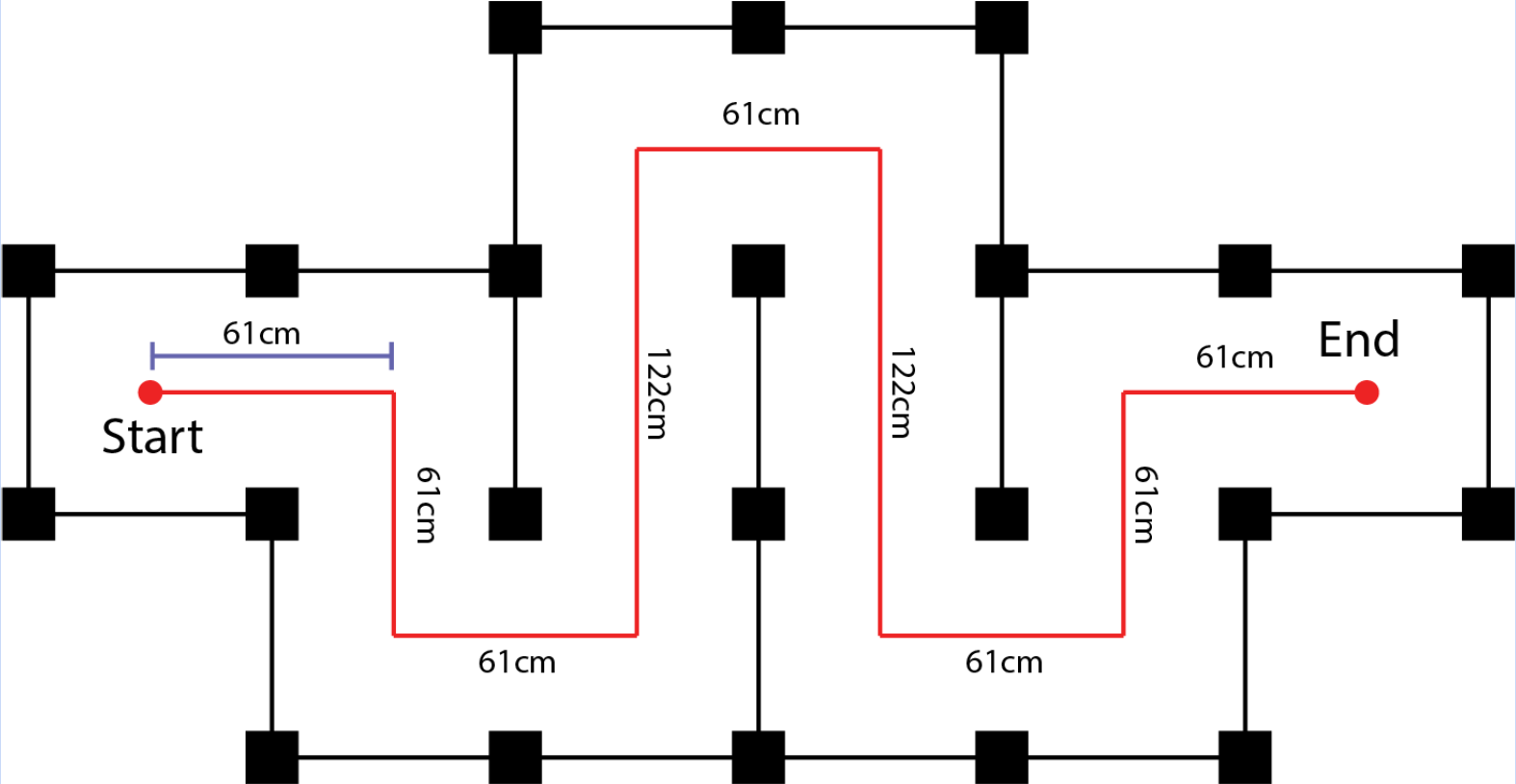
- Run you motion controller to drive the path show in the image above. Include the following items in your submission:
- Record a video of the robot attempting the path at a slow speed (~0.2m/s & pi/4 rad/s) and a high speed (~0.8m/s, pi rad/s) and provide a link to it. The robot motion does NOT need to be perfect
- Include a plot of the (x, y) odometry position as the robot executes the path at both speeds.
- Write a short description of your controllers (1/2 page) and any features we should be aware of.