MBot System Setup
Last Updated: Mar 06, 2026
The following items are needed:
- microSD card
- SD adapter
- A laptop can read and write SD card
Notice #1: You do not need an external monitor during the set up process. However, if you want to connect to external monitor at any point, you need to plug into HDMI-0 port. The Pi5 has 2 HDMI ports, plug into the one closer to USB C port.
Notice #2: This guide will walk you through the steps needed to setup the MBot Classic system. The guide is intended to be followed in order, do not jump back and forth.
Contents
- Contents
- Set up RPi 5 System
- Flash MBot firmware
- Drive the mbot
- Setup mbot_ws
- Test Camera
- Test LiDAR
- Install and test foxglove
- Useful commands
Set up RPi 5 System
1. Flash the image
- Download the custom image
2026-01-15-mbot-ros2-base-ubuntu24.img.gzfrom this link to your laptop. - Download Balena Etcher to your laptop, it is a tool to flash the OS image to the SD card. Plug in the SD card to your laptop using SD card reader then following the steps in Balena Etcher. (The image is 18GB, this can take 15 min).
Once you have the SD card with the OS image flashed on it, don’t insert the SD card in the Pi 5 yet, continue to the next step.
If you do the flashing on a Windows computer, you may see many file explorer windows and error messages pop up when you insert the SD card and when you finish flashing. Those are expected, and you can safely close the file explorer windows and dismiss the error messages. However, if Windows asks you to format the SD card through a popup dialog box, close the message through the “Cancel” button and do not click the “Format Disk” button.
2. Set up system utilities
If the flash was successful, insert the SD card into your laptop, you should see a folder named “system-boot” or something similar based on your laptop’s OS.
Find the file mbot_config.txt on this volume and modify it as follows:
- Set
mbot_hostnamefollowing this format:mbot-<section>-<team#>-<unique_name>- For example: if you are in the AM section team 6, and your unique_name is johndoe, you should name the robot as
mbot-AM-team6-johndoe
- For example: if you are in the AM section team 6, and your unique_name is johndoe, you should name the robot as
- Enter your home Wi-Fi details for
new_wifi_ssidandnew_wifi_passwordif you intend to use it at home later. - Leave all other variables unchanged.
Then save the file. Now you can eject the SD card.
3. Boot the Pi5
-
Insert the SD card into your Pi5. The SD card slot is located on the bottom on the side opposite the USB ports.

- Turn on the power bank and ensure that the power cables are connected as per the assembly guide.
-
Wait for about 1 minute until the OLED screen lights up like the image below, where the IP should be something like
192.168.X.Xmeaning it is part of a local network and not directly accessible from the public internet. Once you see this, you can proceed to the next step.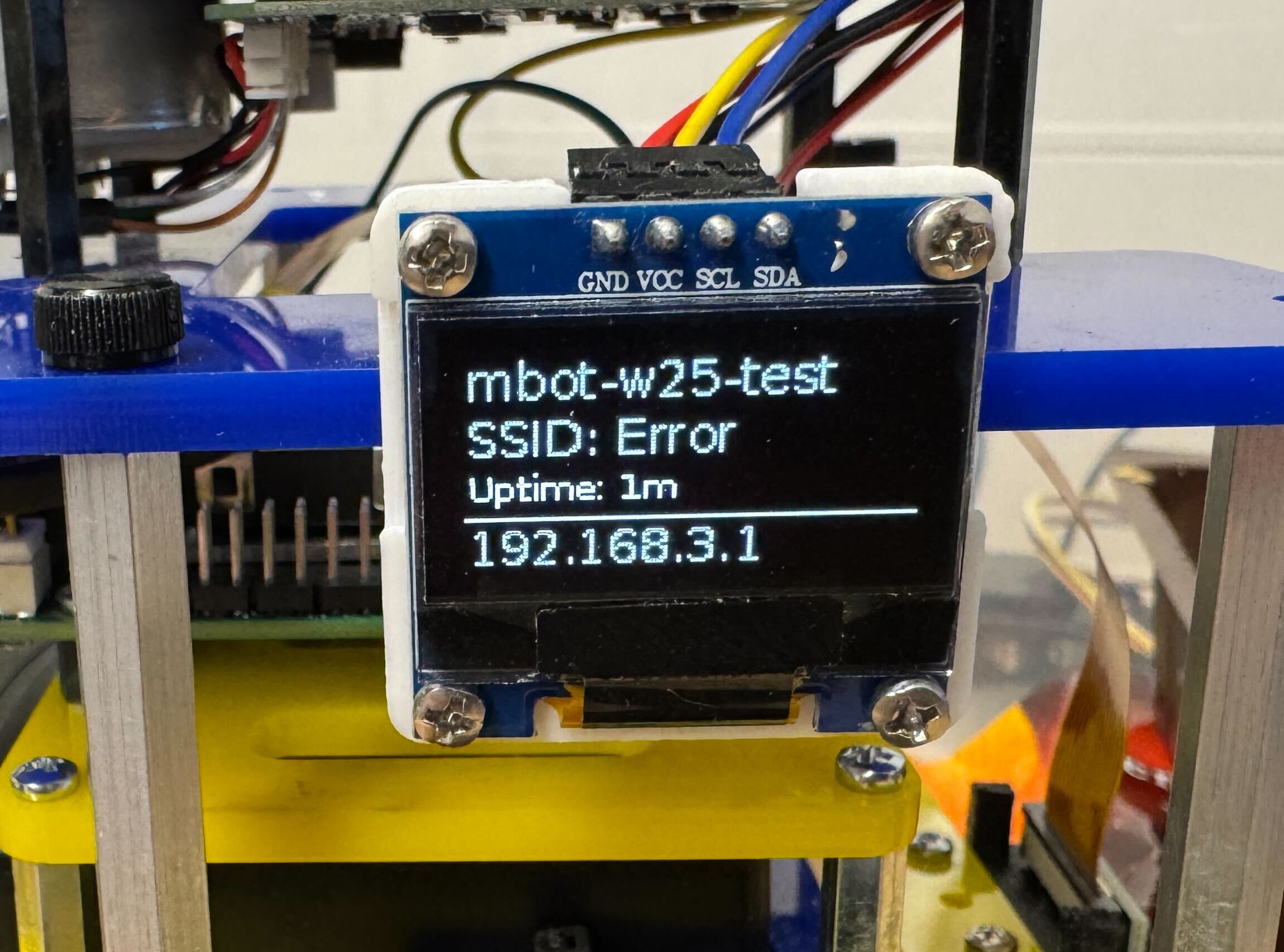
4.1 Connect to the Internet on UM Campus - MWireless
Video Demo:
Steps:
- Connect to the MBot’s local access point. See the instructions on the official MBot website here under the “Connecting to the MBot’s Access Point” section.
- Use NoMachine to access the MBot. Follow the instructions on the official MBot website here.
- Connect the MBot to the Internet. Open a terminal in the NoMachine desktop and run the following commands to connect the MBot to the Internet:
cd ~ ./SecureW2_JoinNow.run - When prompted for your unique name and password, use the 550 course credentials, it will be distributed during lab. Avoid using your own UM credentials for your privacy safety.
- After entering your credentials, NoMachine will disconnect during the process. Close the NoMachine window and wait for about 1 minute. Check the OLED screen to see if the IP address has changed from
192.168.X.Xto a different one. This indicates that the MBot has successfully connected to the Internet.- If the OLED screen says “IP Not Found” or “Error” and has been that way for over two minutes, you aren’t connected to the network, you might have typo when input the UM account password, find GSIs and ask to connect to an external monitor.
- If you encountered issue with “license expired”, use the following command to set the time back one year to trick the script:
sudo date -s "2025-01-01 12:00:00"
4.2 Connect to the Internet at Home
-
Ensure the
new_wifi_ssidandnew_wifi_passwordare correctly set in thembot_config.txtfile (check for any typos). They should be your home wifi name, and home wifi password. -
Start the MBot, wait for about 1~2 minute, please be patient. You may hear the fan start a couple of times, and eventually, the OLED screen will display the MBot’s IP address (since you are at home, the IP be
192.168.x.xis normal unlike on campus), meaning the mbot is connected to your home Wi-Fi.
If you have successfully connected your MBot to MWireless or your home Wi-Fi, you can use its IP address to remotely access the MBot. From now on, you can always find the IP address on the OLED screen. Proceed to the next step for more details.
5. Remote Access
At this point, your laptop functions only as a gateway for the SSH connection to your MBot. All programming is executed on the MBot, all the commands should be run in the MBot terminal, not on your laptop.
To access the mbot, your laptop and the MBot must always be on the same network. And there are 2 options to connect:
Username: mbot
Password: i<3robots!
6. Change your mbot’s password
For mbot network security, you may change your password once you have set up your mbot. The default password is i<3robots!, which everyone uses. Here’s how to change your mbot’s password:
- SSH to the mbot using VSCode or your laptop terminal.
- Enter this command in the mbot terminal:
passwd. You will be prompted to enter your current password. - Next, you will be asked to enter your new password and retype it to confirm.
-
If the passwords match, you will see a message indicating that your password has been updated successfully.
The output will look like this:
 mbot@mbot-0018-shaw:~ $  passwd
 Changing password for mbot.
 Current password:
 New password:
 Retype new password:
 passwd: password updated successfully
Flash MBot firmware
In this session, we are going to work on setup of the Control Board, which is the board located at the bottom of the mbot.
1. Compile the firmware
- Go to the Class GitLab page, and find
mbot_firmware_rosrepository. - Fork it to your GitLab group.
- Clone the forked repository to your home directory.
# cd to the home directory cd ~ git clone your_group_forked_url- When we say
your_group_forked_url, we mean the URL shown in the image. Go to your group’s forked repository on GitLab, click Code, and copy that URL.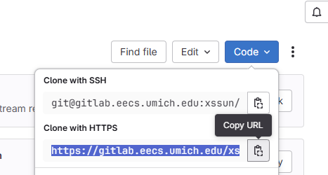
- When we say
- Compile the firmware files.
# cd to the firmware folder cd ~/mbot_firmware_ros # create the build folder mkdir build cd build # compile the firmware cmake .. make- After it’s done,
~/mbot_firmware_ros/builddirectory is going to have all the executables we need.
- After it’s done,
2. Calibrate the MBot and flash the firmware
In this step, we are going to calibrate the mbot and then flash the firmware.
- Place the MBot on the floor in a spot with at least 2 feet of clear space around the robot, preferably on the same type of surface you plan to use it on.
- First, flash the calibration file to calibrate your MBot.
cd ~/mbot_firmware_ros/build sudo mbot-upload-firmware flash mbot_calibrate_classic.uf2mbot_calibrate_classic.uf2is one of the files we compiled from step 1. Expected output:$ sudo mbot-upload-firmware flash mbot_calibrate_classic.uf2 [sudo] password for mbot: Detected Raspberry Pi 5, entering flash mode... Flashing action for mbot_calibrate_classic.uf2... Loading into Flash: [==============================] 100% The device was rebooted into application mode.Here is a video showing the expected calibration routine:
- Allow the Pico to finish its calibration routine without interference. The calibration script will save the parameters onto the Pico’s memory.
- Then, you can flash the firmware that will run on the Pico during operation.
sudo mbot-upload-firmware flash mbot_classic_ros.uf2
If you didn’t see the expected output above, but having the following output:
No accessible RP-series devices in BOOTSEL mode were found.
- Check if all the cables are connected correctly (USB-C from Pico to Pi; Pico’s power cable; the GREEN/WHITE jumper wire to the control board).
- If all the cables are connected, please use the “Manual Boot Mode” in this tutorial to flash the firmware.
3. Minicom to verify the flash operation
Minicom is a program designed for serial communication that connects devices to a Linux PC via serial ports, we will use Minicom to read the pico printouts during the flash process.
- After flashing the firmware to the Pico, run the following command to start minicom
sudo minicom -D /dev/mbot_debug -b 115200You should see output like this:
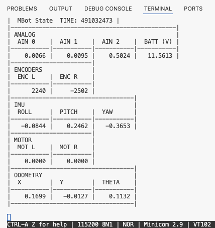
- Successful Firmware Flashing: After flashing the firmware successfully, Minicom will display the table above. Manually turning the wheel will update the encoder counts in the Minicom terminal. All these are calculated and displayed by the firmware.
- Common confusion: When both wheels rotate forward, the left wheel encoder counts and motor velocity (
ENC LandMOT L) increase positively, whileENC RandMOT Rare negative. Why aren’t they both positive?- This is the expected behavior. The wheel frames have their z-axes pointing outward, so based on right hand rule, rotating the right wheel forward corresponds to a negative rotation about its local z-axis. One purpose of calibration is to ensure the signs are correct and consistent with the coordinate definitions.
- Common confusion: When both wheels rotate forward, the left wheel encoder counts and motor velocity (
- Unsuccessful Firmware Flashing: If the firmware doesn’t flash correctly, repeat the calibration and firmware flashing steps. This time, open a second terminal window with Minicom running, so we can monitor its outputs for debugging. If there was an error, take a screenshot and send to the GSIs for better troubleshooting.
- Successful Firmware Flashing: After flashing the firmware successfully, Minicom will display the table above. Manually turning the wheel will update the encoder counts in the Minicom terminal. All these are calculated and displayed by the firmware.
- To exit Minicom, press
CTRL + A, then pressX, then pressEnterto quit.
Drive the mbot
Run the following command in the VSCode terminal:
ros2 run teleop_twist_keyboard teleop_twist_keyboard
- Press
xa few times to reduce the linear speed to 0.2, so the robot doesn’t sprint out. - Use your keyboard to drive the robot. As shown in the terminal:
i= forward,= backwardj= turn leftl= turn right
If you’ve successfully driven your robot around, your control board setup is complete!
- If the robot does not drive straight forward when you press
iand instead turns, but your calibration results look correct and the minicom table shows reasonable motor velocities, then the issue is likely related to the PID gains. We will address PID tuning in Checkpoint 1, so don’t worry about this for now.
Setup mbot_ws
This repository contains hardware ROS drivers, custom ROS messages, MBot URDF files, and the other ROS packages.
- Go to the Class GitLab page, fork the
mbot_ros2_wsrepository to your group, and clone it to your mbot home directory.cd ~ mkdir mbot_ws cd ~/mbot_ws git clone --recurse-submodules your_group_url src- The repository is called
mbot_ros2_ws, but here we clone it into~/mbot_ws/src, the repo’s name is irrelevant.
- The repository is called
- Run the following commands:
cd ~/mbot_ws # Update package list sudo apt update # install ros dependencies rosdep install -y --from-paths src --ignore-src --rosdistro $ROS_DISTRO --skip-keys=libcamera # build the packages colcon build --symlink-install # source the env echo "source $PWD/install/local_setup.bash" >> ~/.bashrc source install/local_setup.bash- There might be warnings after running colcon build from sllidar_ros2 package:
1 package had stderr output: sllidar_ros2, it is normal, if you re-run the command the warnings will be gone.
- There might be warnings after running colcon build from sllidar_ros2 package:
Test Camera
Test your camera by going through the following steps in order. If any of the steps produce unexpected results, contact the GSIs for assistance.
- To test if camera is detected, run this in the VSCode terminal:
rpicam-hello- If the terminal didn’t say “ERROR: ** no cameras available **”, your camera is detected. Everything is good, use
ctrl+Cto quit.
- If the terminal didn’t say “ERROR: ** no cameras available **”, your camera is detected. Everything is good, use
- To test if camera is working, run:
cd ~ rpicam-still -t 1 -o test.jpg- This will take a photo and save it in the home directory, you can use VSCode to check the photo. The photo will be upside-down, that’s expected.
- To test if camera ROS driver is working, run the following in the VSCode terminal:
# bring up the camera node and flip the image ros2 run camera_ros camera_node --ros-args \ -p orientation:=180 \ -p width:=640 -p height:=480 \ -p format:=BGR888- Ignore the errors about calibration files.
- You can visualize the camera view in rqt on NoMachine desktop. Run the following in the NoMachine Terminal:
ros2 run rqt_image_view rqt_image_view - Select the image topic
/camera/image_raw
Do not hot-swap the camera! Hot swap will leave the camera on ghost state. If you need to replace the camera, the correct procedure is: Power OFF → Wait 30 seconds → Swap cameras or Re-insert ribbon cable → Power ON
Test LiDAR
- Run the following in the VSCode terminal:
ros2 launch mbot_bringup mbot_bringup.launch.py- This will bring up the lidar driver, the robot description for visualization, and the static tf.
- Run the following in the NoMachine Terminal:
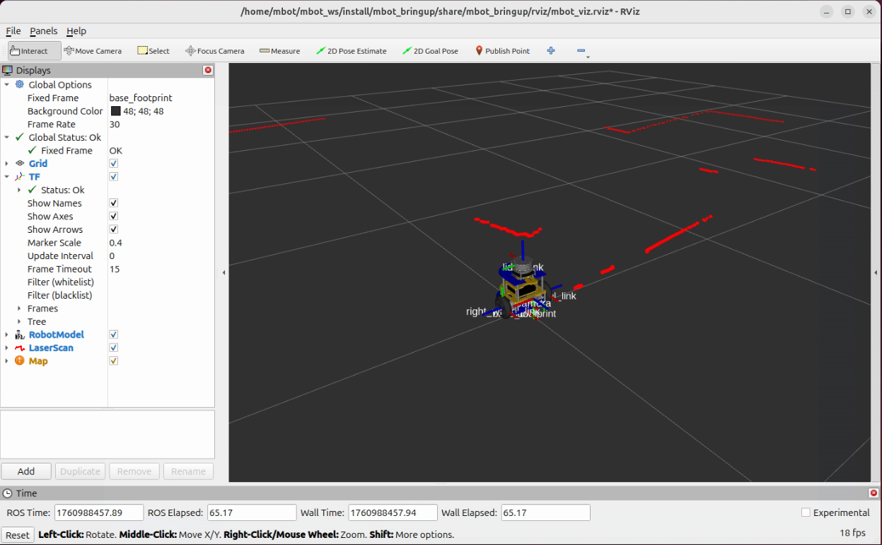
ros2 launch mbot_bringup mbot_viz.launch.pyYou should see the RViz open up with the robot model and the LiDAR scan show up. And if you look closely, the lidar scan is actually “floating”, because it is shooting out from the lidar frame.
Install and test foxglove
Install Foxglove bridge, a web-based visualization tool as an alternative to NoMachine. Use foxglove will save at least 50% CPU usage.
sudo apt update
sudo apt install ros-$ROS_DISTRO-foxglove-bridge
Test:
- Go to: foxglove -> Sign in with Google -> Sign in with you UM account
- Run the Foxglove bridge in the VSCode terminal:
ros2 launch foxglove_bridge foxglove_bridge_launch.xml - Run the following in the VSCode terminal:
ros2 launch mbot_bringup mbot_bringup.launch.py - Open connection -> Foxglove WebSocket -> Replace
localhostwith your IP address -> Open - If you use chrome, foxglove will pop up a window, follow the instruction there.
Demo video:
Useful commands
Turn LiDAR ON/OFF
This LiDAR switch command is for the mbots that have done the hardware setup, in which the LiDAR is powered through the Bottom Board’s SV3 slot.
If you don’t need the LiDAR but it keeps spinning (which is loud and drains the power bank), you can turn it off using the following command:
# Turn the power off
ros2 service call /lidar_power std_srvs/srv/SetBool "{data: false}"
To turn the LiDAR back on:
# Turn the power on
ros2 service call /lidar_power std_srvs/srv/SetBool "{data: true}"
Reset odometry
If you need to re-run motion controller test, or slam test, or any tests, and the odometry has already accumulated drift, you can reset all odometry calculations back to zero by:
ros2 service call /reset_odometry std_srvs/srv/Trigger