Checkpoint 1
Last Updated: Jan 08, 2026
The first checkpoint is meant to be an introduction to using the GUI of the lab and to start working with the RGB-D camera. The interaction with the GUI will be under the Basic Motion section of the checkpoint, and the interaction with the RGB-D camera will be through the Camera Calibration portion of the checkpoint.
Contents
Basic Motion
Intro
As you will be interacting with the control station GUI for most of the lab, it is important for you to understand how it works and how to interface with it. To start the GUI, following the instructions from the setup guide.
The control_station program launches three threads:
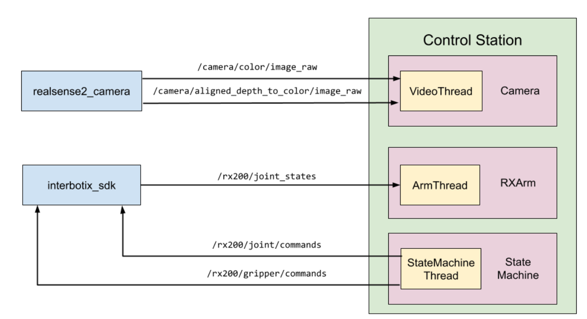
- The Realsense RGB-D camera is handled in its own thread when the node is launched. We refer to this as the VideoThread. The objective of this thread is to capture and display the RGB and Depth images from the ROS topics camera.
- The controlling state machine is run in the StateMachineThread. The objective of this thread is to follow a set of commands and states dictated by the state machine that you will develop throughout this lab.
- Data from the 5-DOF are stored in an RX200 arm object. This process is run in the RXArm Thread.
There are 2 ways to control the arm:
-
Manual Mode
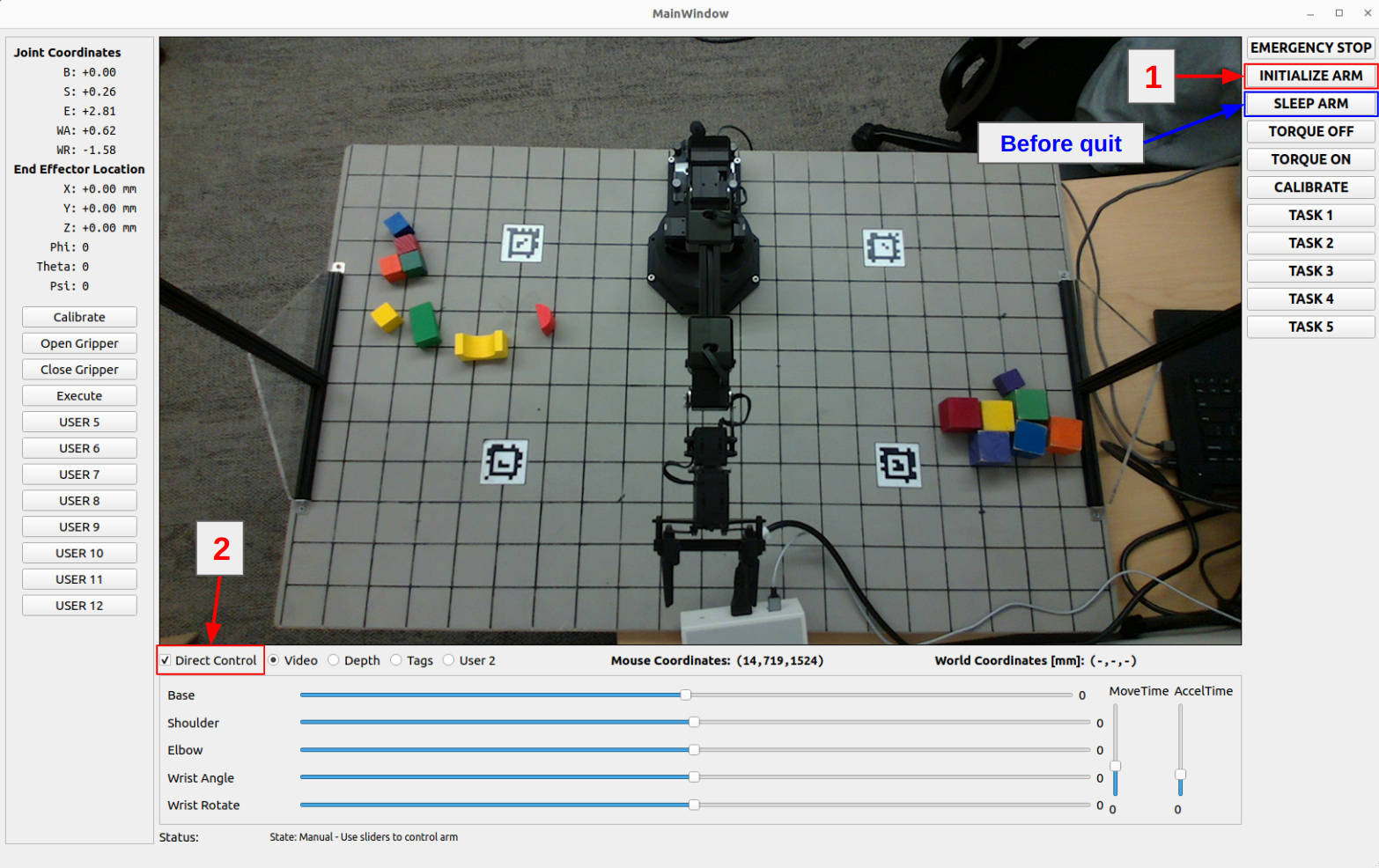
- First, click on “INITIALIZE ARM” to set the arm to its initial position. This will allow you to check the “Direct Control” box and use the slider. Moving the slider will adjust all joints of the arm.
- Use “Open Gripper” and “Close Gripper” anytime to control the gripper.
Always remember to SLEEP ARM before ending the arm node or the arm will crash to the board and may break!!!
-
Autonomous Mode
Autonomous mode involves the design of the state machine. For this mode, which you will work on later in this lab, you will design a state machine that can be executed upon clicking a button on the GUI. Implementations of these state machines will be done in
src/state_machine.py.
Task 1.1 Control Station GUI
Have team members try to pick up a block manually using the sliders and the open/close gripper buttons on the control station GUI.
Task 1.2 Waypoints Following
Implement the execute state and associate it with the execute function in src/state_machine.py. Use the existing function execute(self) in this script for your implementation.
- In the function, set up a simple waypoint follower that executes the plan below by using the
self.rxarm.set_positions()function, and usestime.sleep(t)for a reasonable amount of time for the arm to get to the waypoint. - At the end of the function, set
self.next_stateequal to"idle"to transition back to the idle state. - The configuration space waypoints the arm should follow are given below and are stored as
self.waypointsin thesrc/state_machine.pyscript as well.
[[       -np.pi/2,     -0.5,     -0.3,          0.0,         0.0],
 [0.75 * -np.pi/2,      0.5,      0.3,     -np.pi/3,     np.pi/2],
 [ 0.5 * -np.pi/2,     -0.5,     -0.3,      np.pi/2,         0.0],
 [0.25 * -np.pi/2,      0.5,      0.3,     -np.pi/3,     np.pi/2],
 [            0.0,      0.0,      0.0,          0.0,         0.0],
 [ 0.25 * np.pi/2,     -0.5,     -0.3,          0.0,     np.pi/2],
 [  0.5 * np.pi/2,      0.5,      0.3,     -np.pi/3,         0.0],
 [ 0.75 * np.pi/2,     -0.5,     -0.3,          0.0,     np.pi/2],
 [        np.pi/2,      0.5,      0.3,     -np.pi/3,         0.0],
 [            0.0,      0.0,      0.0,          0.0,         0.0]]
If the self.waypoints value in the code differs from the value on this site, please consider the information on this site as the most current version.
When you click on “Execute” or your newly defined button, your arm should follow the waypoints above and eventually back to sleep position. Successfully doing this indicates that you have completed task 1.2.
Task 1.3 Teach and repeat
Teach and repeat is a common technique for programming robotic arms to carry out repetitive tasks. It’s user-friendly, allowing control of the robot without needing advanced skills. The task at hand is to create a system that interprets a set of distinct waypoints in the robot’s joint space, guiding the arm along a path that connects these points.
Your objective for this task is to get comfortable with the codebase. This means learning how to make the robot move to certain joint positions. Getting this right is essential for your future tasks in kinematics. To make the arm move smoothly, you will want to check the angular displacements of each joint between waypoints and generate move_time and accel_time parameters for the set_joint_position command so the largest joint displacement moves consistently at some maximum angular speed.
Building on task 1.2, where you executed the provided waypoints, your next step is to ‘teach’ the robot the pattern you want it to follow. This process involves recording the robot arm’s joint positions at specific locations. Your task now is to implement this feature in the GUI. You have the freedom to choose the implementation method, but ensure it is user-friendly and intuitive.
Instruction:
- Implement the “teach-and-repeat” feature using buttons to control the state machine. Begin by setting the arm to idle mode (torque off). Then, manually guide the arm through its workspace, recording a series of waypoints in configuration space. To record, consider adding new buttons in the GUI specifically for this purpose. These waypoints will define the path for the arm to follow. Additionally, integrate controls for opening and closing the gripper as part of the sequence.
Hints:
- To be able to move the robot manually, set torque off via the GUI.
- To create a button on the GUI, you can edit the
src/control_station.pyscript, and use the block of code under “User Buttons” as a guide. - Consider utilizing the status message bar at the bottom of the GUI window to provide instructions or using it for your own debug purpose.
1) Cycle Task: Teach your robot to cycle swapping blocks at locations (-100, 225) and (100, 225) through an intermediate location at (250,75). Coordinates are in mm, relative to the world frame. See the board diagram.
2) Report how many times you can cycle (if you can do 10, feel free to stop) and include a plot of joint angles over time for 1 cycle. Hint: Use ros2 bag to record the /rx200/joint_states topic and the rosbags python module to parse the recorded bag.
Optional: include a 3D plot of the end effector position by sending recorded joint angles through your FK equations.
Anyone using your control station should be able to manually move the arm and record waypoints by clicking on your GUI. After recording, they should also be able to execute the path-following feature through the GUI interface. Successfully accomplishing this indicates that you have completed task 1.3.
Camera Calibration
For this part, you will be performing a camera calibration process:
- Find the intrinsic matrix for the Realsense camera by using the ROS camera calibration package and provided checkerboards.
- Using physical measurements come up with a rough extrinsic matrix for the camera.
Task 1.4 Intrinsic Camera Calibration
The camera comes with an internal factory calibration, and this information is published by the camera’s ROS node. You can access it by echoing the ROS topic using following commands:
# list all the topics available
ros2 topic list
# echo the specific topic
ros2 topic echo /the_topic_you_want_to_check
- The k matrix from camera info usually means intrinsic matrix.
To perform the intrinsic calibration, use the ROS camera calibration package, which should already been installed from the setup guide.
- You can find official documentation on how to use the camera_calibration package with a checkerboard here. You do not need to run any of the commands in that guide, it is provided solely as a reference for how the package works.
- To do the calibration, you need to:
- Firstly start the Realsense2 node
ros2 launch realsense2_camera rs_l515_launch.py - Then start the camera calibration node:
 cd ~/image_pipeline
 source install/setup.bash
 # the size of the checkerboard and the dimensions of its squares may vary
 ros2 run camera_calibration cameracalibrator --size 6x8 --square 0.025 \
  --no-service-check --ros-args \
  -r image:=/camera/color/image_raw  \
  -p camera:=/camera
- Firstly start the Realsense2 node
- Quickly move the checkerboard through a variety of tilts and positions so the bars fill up. You don’t want this to take too long or the calibration process will hang forever.
- As soon as the “Calibrate” button lights up, click it.
- When you start the calibration process, the window will display that it is not responding and will give you the option to “Force Quit” or “Wait”. Be patient! Do not force quit the application, as it is working in the background, albeit slowly.
- After a minute or so, the calibration results will print to the terminal. If you have waited more than 2 minutes and nothing happens, try again or ask for help.
Notes:
- The ROS camera calibration package will also identify lens distortion parameters, which can be used to reduce video distortion. However, this might not be essential since the Realsense camera usually has low distortion in the imaging area of interest. The distortion for the depth camera is unknown.
- Make sure that you save the calibration values obtained from this process.
Record your average intrinsic calibration after performing the checkerboard calibration 3-5 times. Compare it to the factory calibration.
Question to consider:
1) How do the matrices compare?
2) Do you trust your own calibration or the factory calibration more?
3) What are the sources of error and how large are they?
Task 1.5 Extrinsic Camera Calibration
Using physical measurements of the lab apparatus, come up with a rough extrinsic matrix for the camera. Use the extrinsic matrix and the camera intrinsic matrix to map image coordinates (u,v,d) to world coordinates. Have them displayed in the GUI. A pixel in the depth image from the ROS driver is a 16-bit integer representing a distance from the camera frame in millimeters.
There are two possible ways of finding the rotation of the camera. The first way is accurate enough for our purposes. You only need to do option 2 if you are personally interested in how to get the best possible calibration accuracy.
- (Easy, Less Accurate) Use your phone as a protractor and measure the tilt of the camera relative to the horizontal.
- (Hard, More Accurate) You may also use the
realsense-viewerprogram to find a readout of the camera’s accelerometer, which should give you an approximation of the orientation of the sensor. Launch the program by runningrealsense-viewerin the terminal. To see the accelerometer, enable the Motion Module then click on the “2D” text on the top right.
Assumptions:
- X axis of the world frame are parallel to U axes of the sensor
- YZ plane of the camera frame is parallel to the YZ plane of the world
- Camera frame is at the front surface of the sensor
Record your extrinsic matrix
Checkpoint Submission
- Task 1.2
- Record a video of your robot playing back the waypoints
- Task 1.3
- Demonstrate the teach-and-repeat in a video by recording the process of teaching the robot and repeating at least once the cycle task from the “required for the report” subsection
- Task 1.4/1.5:
- Report your factory and calibrated camera intrinsic matrices.
- Record a screenshot or video of the GUI reporting world coordinates of the mouse cursor when hovering over the image using the intrinsic and extrinsic calibrations.
- Record the reported position (x,y,z) of the center of the top of a stack of large blocks placed at the following locations for a stack size of [0,1,2,4,6] blocks (total of 20 measurements): (0,175), (-300, -75), (300, -75), (300, 325)