Top Plate
Last Updated: Sep 09, 2024
This guide is for Differential Drive MBot Classic.
Contents
1. RPLidar
-
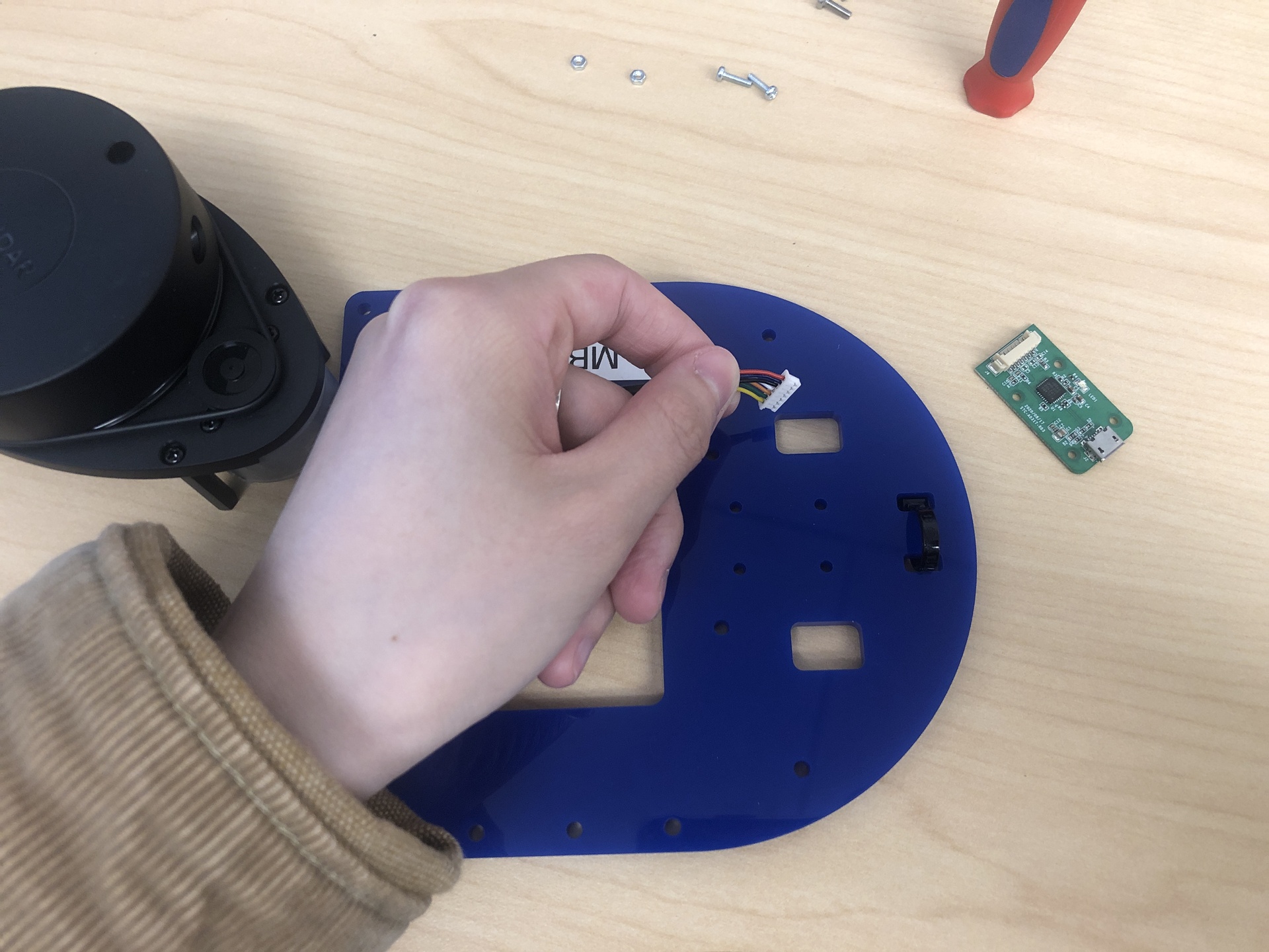
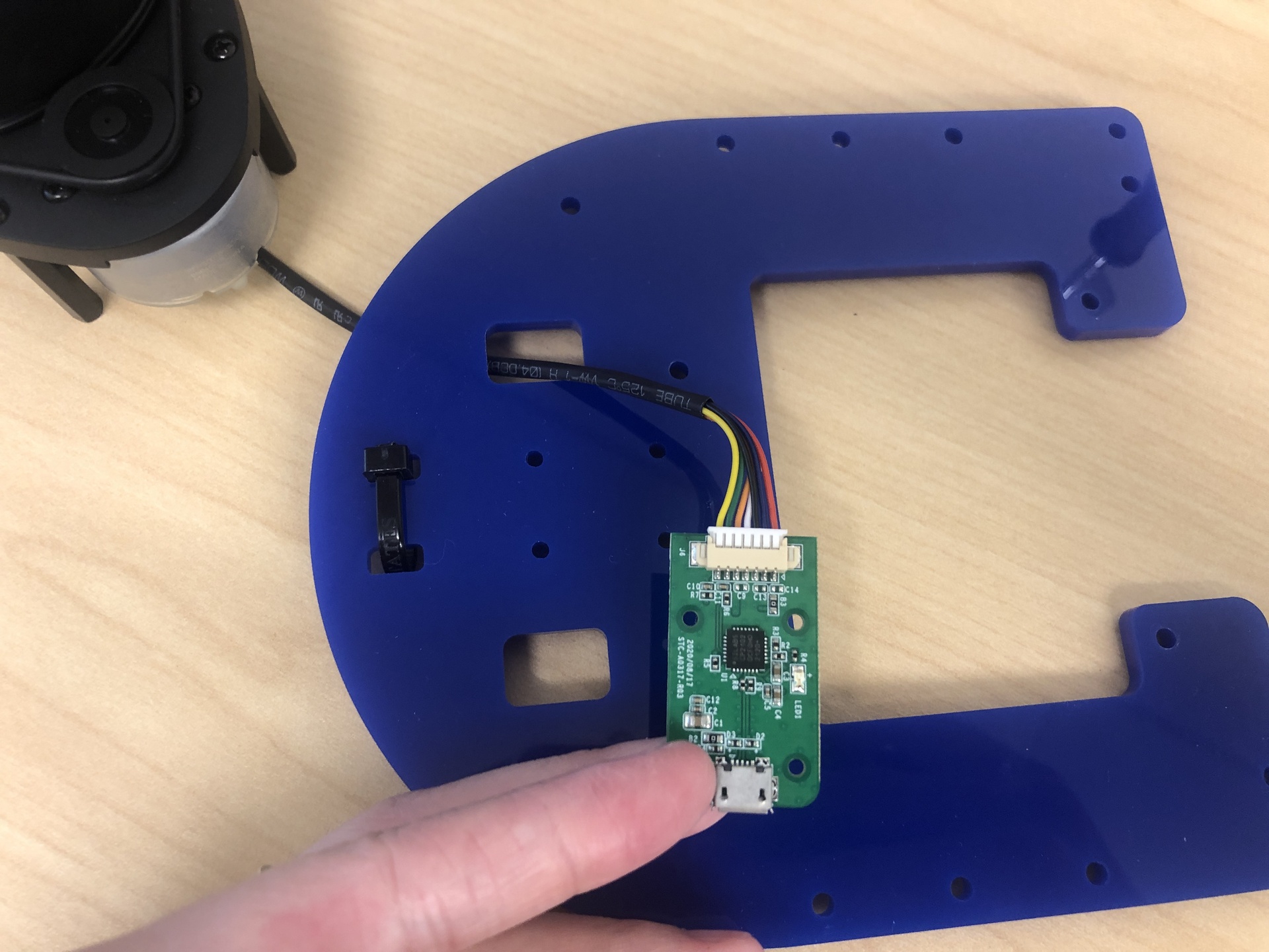
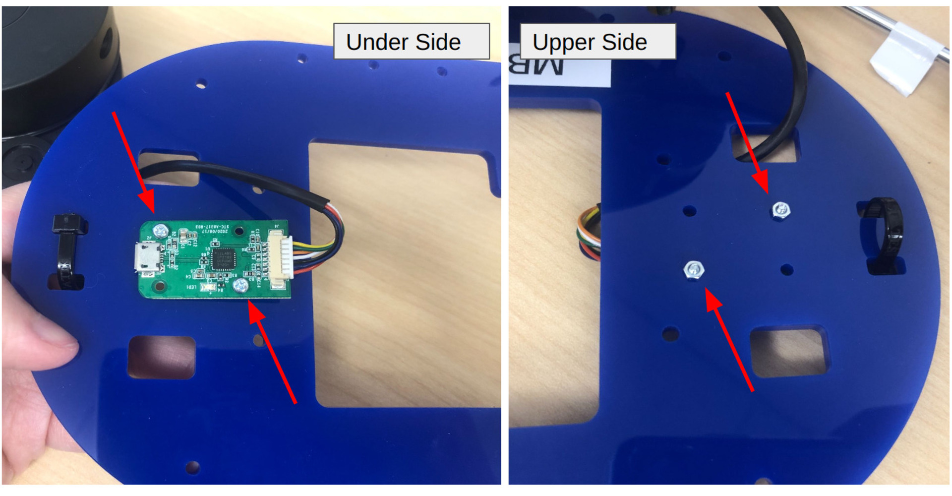
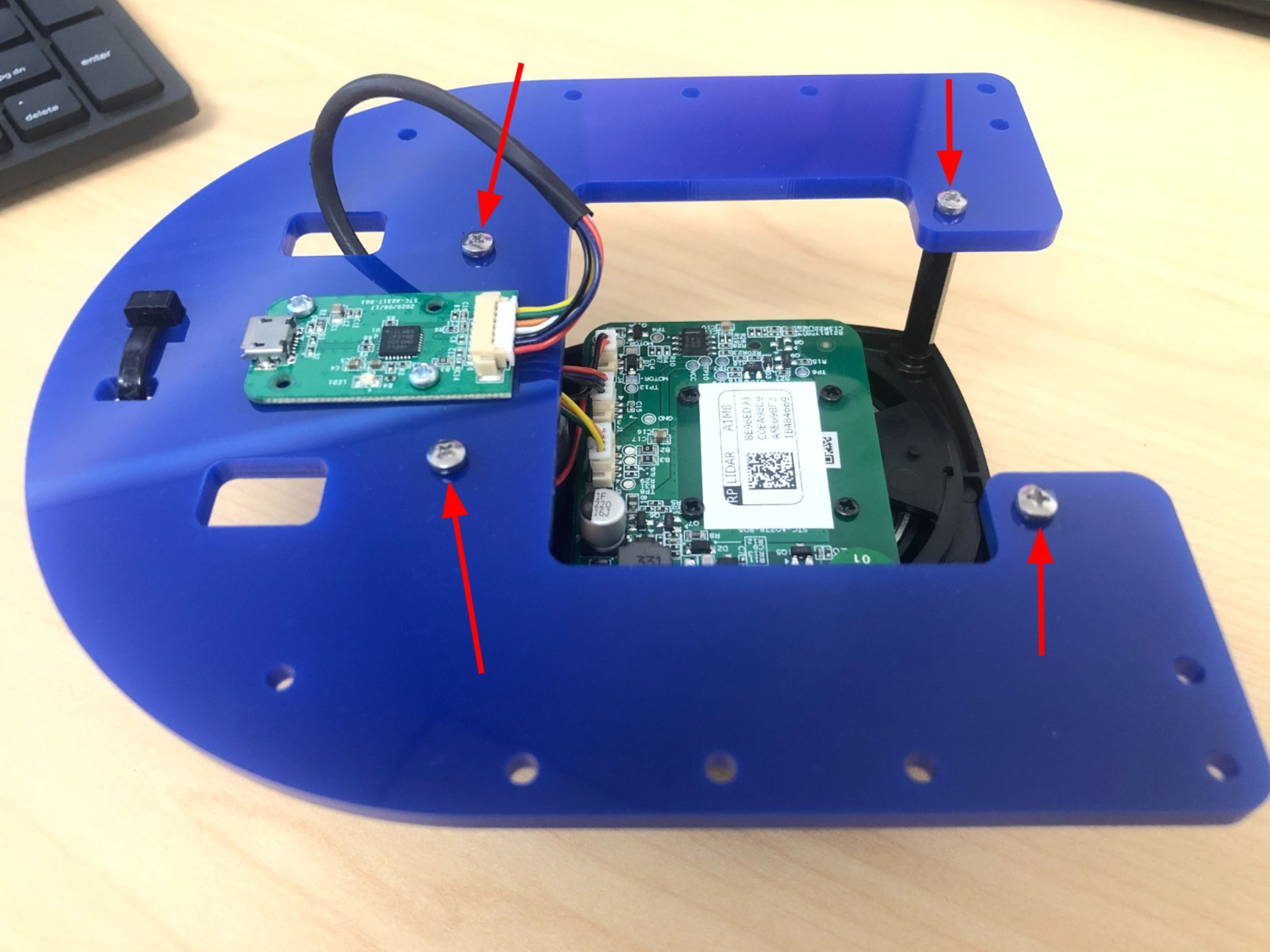
Attach RPLidar USB Interface to top plate
Components # M2 x 8mm Screws 2 M2 Nuts 2 RPLidar kit 2 Begin by passing the cable through one of the square holes on the board, and plug the connector into the USB Interface. Secure the USB Interface to the plate using two sets of M2 screws and nuts. The side the USB Interface attached, is the under side.
-
Attach the RPLidar to the upper side of the plate
Components # M2.5 x 8mm Screws 4 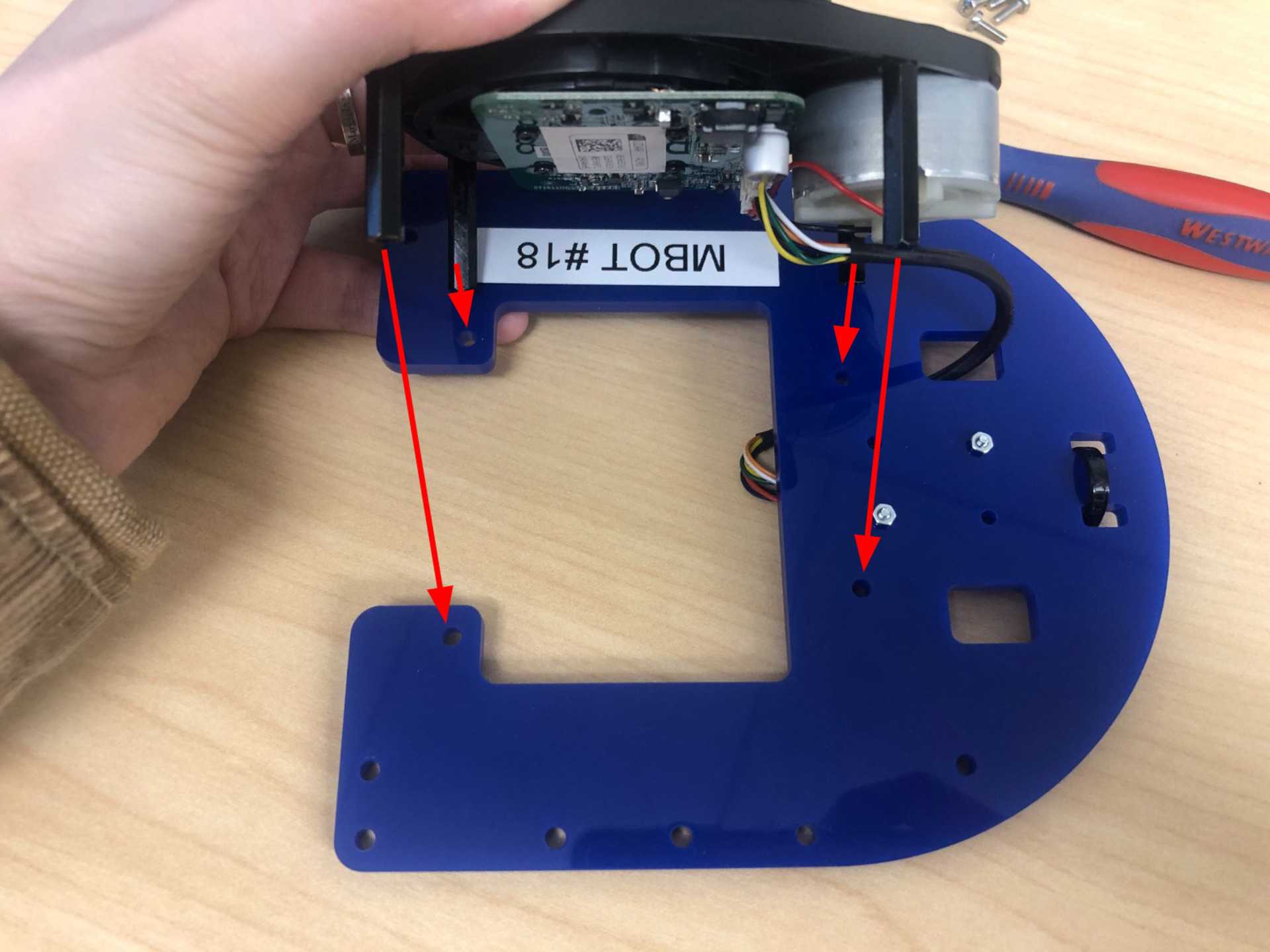
-
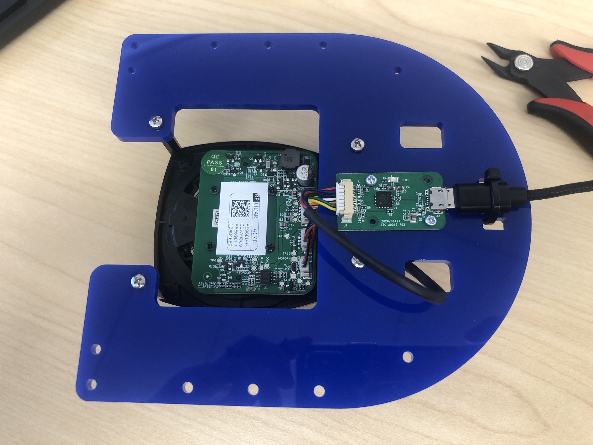
Plug in the USB cord to the RPLidar USB Interface, and fastening it with a zip tie. Cut the extra length off.
Components # 9” USB Micro Cable 1 zip tie 1 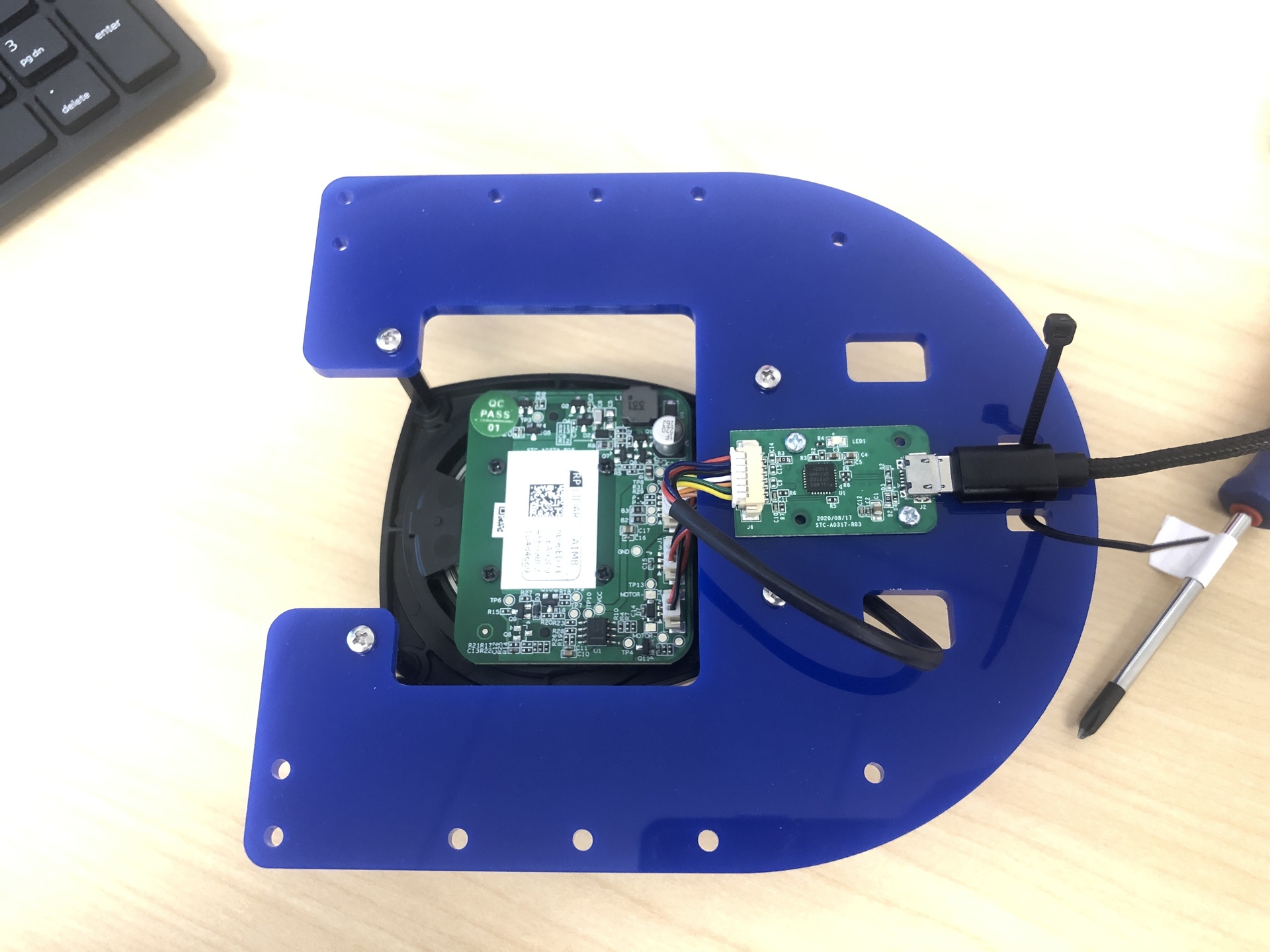
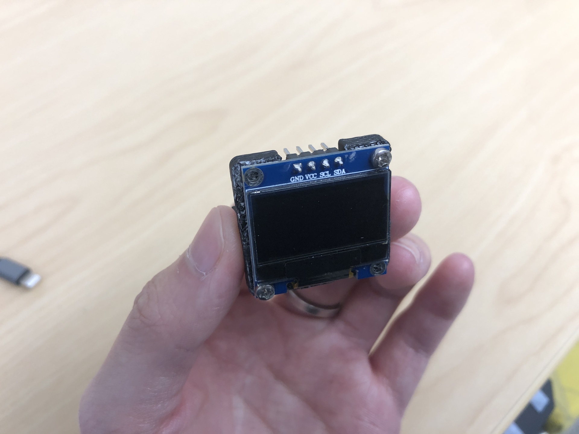
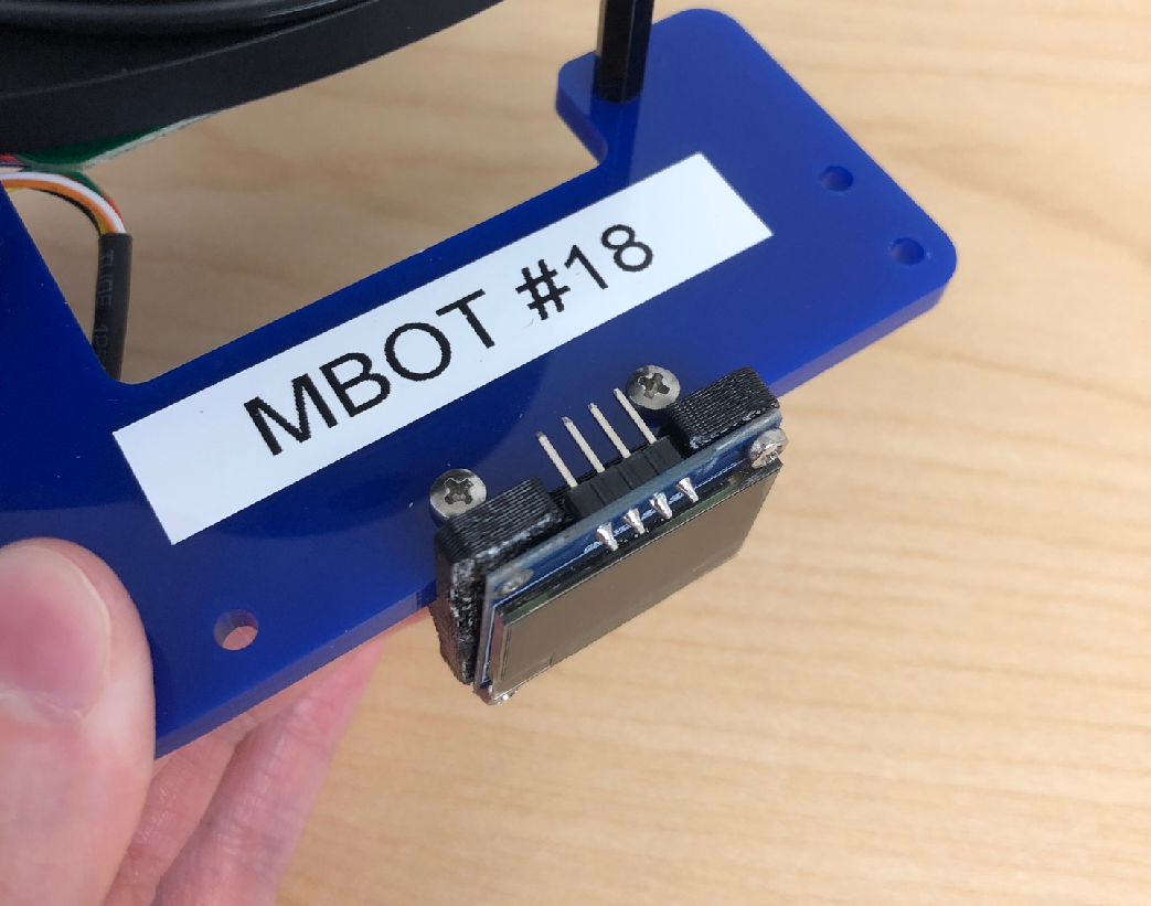
2. OLED Screen
| Components | # |
|---|---|
| OLED screen | 1 |
| OLED mount | 1 |
| M2 x 8mm screws | 4 |
| M2.5 x 8mm screws | 2 |
| M2.5 threaded inserts | 2 |
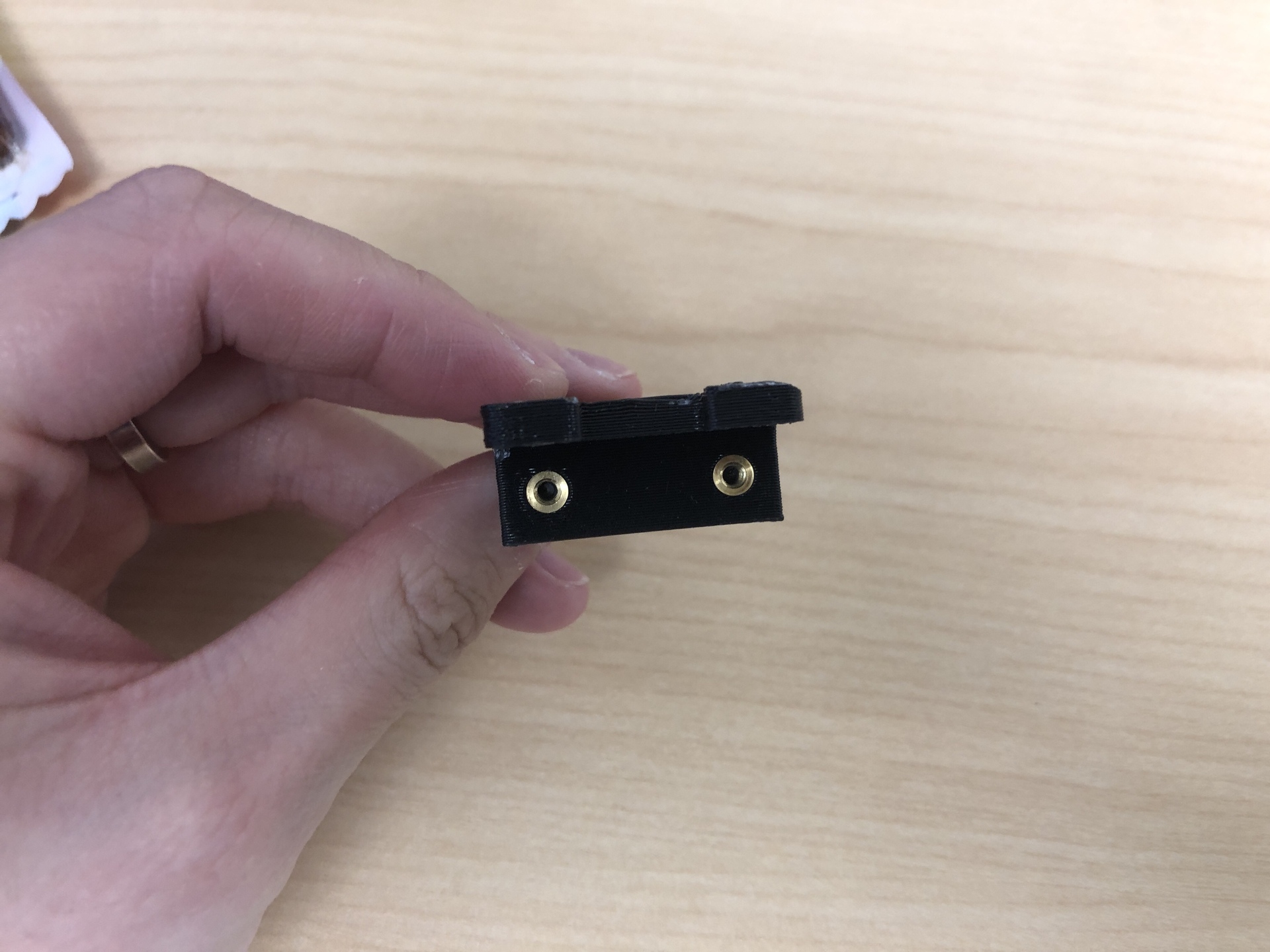
Note that the OLED mount and the camera mount are both white and look similar, but they are different!
- Insert the threaded inserts into the OLED mount, you need soldering iron for this to heat up the inserts.
- Secure the OLED screen to the mount using four M2 x 8mm screws.
- Attach the mount to the right side of the robot using M2.5 x 8mm screws.
3. Assemble 3-heads jumper wire cable
| Components | # |
|---|---|
| jumper wires (Black/Red/Yellow/Blue/Green/White) | 6 |
| Crimp connector housings (3/4/6 pins) | 3 |
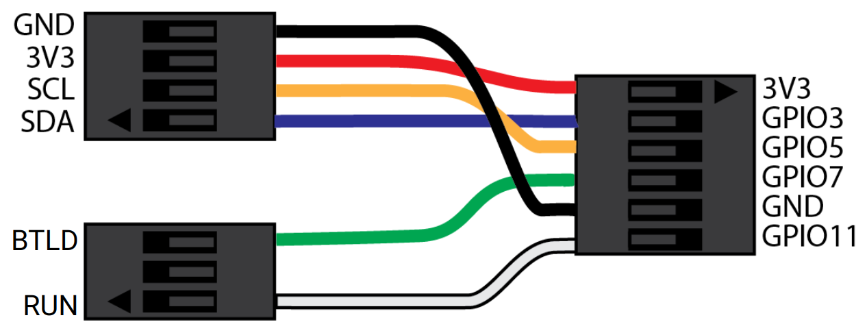
You will need to build the OLED/Bootloader cable assembly as shown. This cable has three heads, which plug into the following:
- Raspberry Pi header (6-pin header)
- OLED module (4-pin header)
- Control board (3-pin header)
This cable allows communication with the OLED and controls the run and bootload modes on the control board.
Assemble the 3-heads wire as depicted in the image. Color and order matters! Your assembled wire should look exactly like the image indicated.
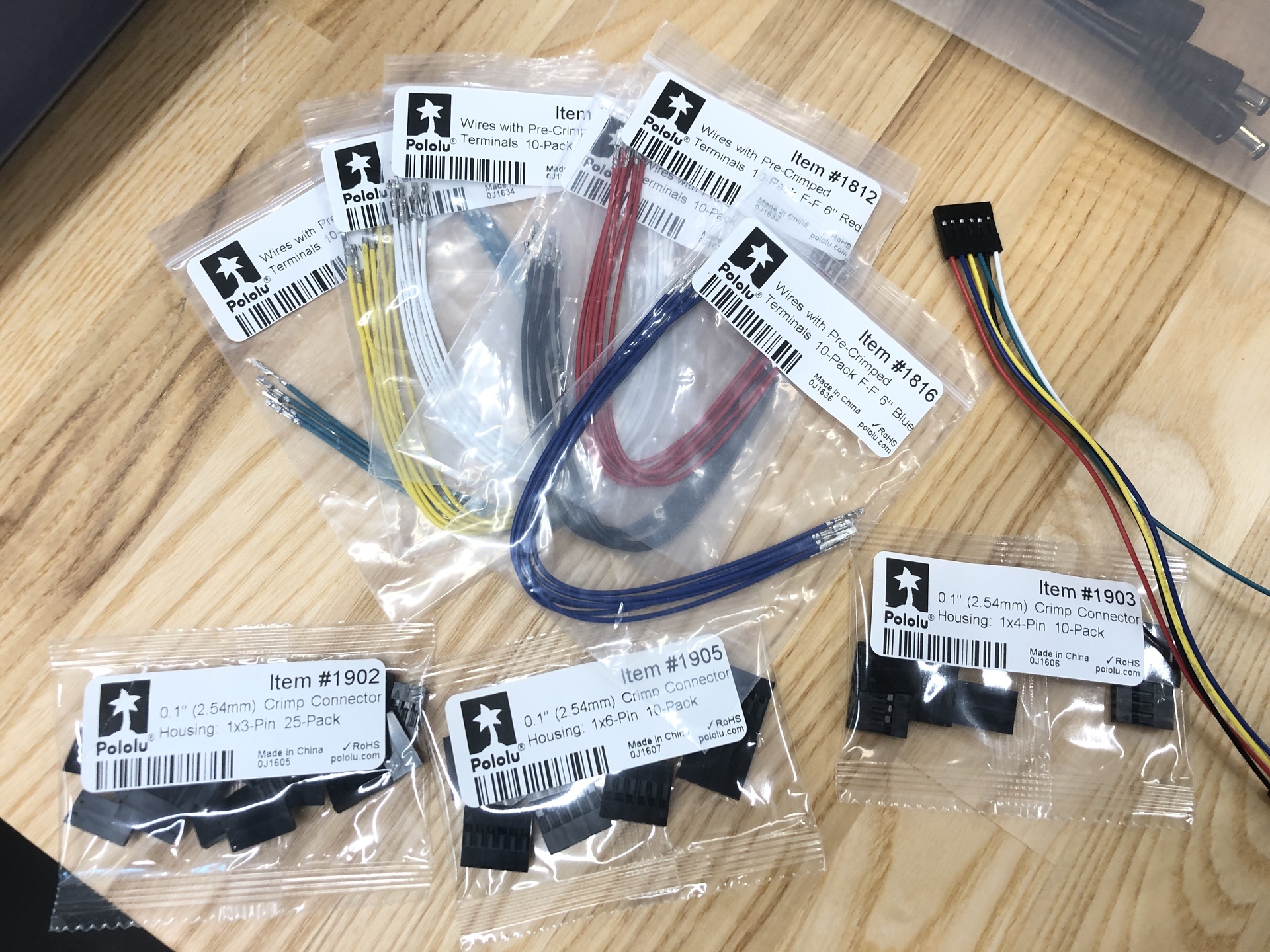
After assembling the wires, do not plug them in yet.
Now, let’s move on to the wiring section.