MBot Hardware Setup
Last Updated: Jan 13, 2026
This guide is for ROS2 MBot Classic running firmware v1.1.4 and above.
Your MBot may arrive fully assembled or in three parts.
- If it is not fully assembled, follow the MBot Assembly Guide and complete Steps 1–3 only. Stop before the final wiring.
At this point, your MBot is mechanically assembled but not wired. Follow this page to complete the remaining wiring.
Extra Wiring Step: LiDAR Power Update
-
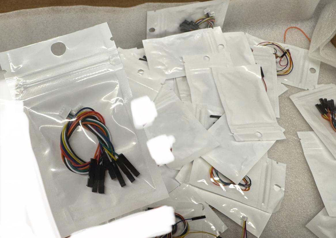
Find the LiDAR power cable in the lab.
- Remove the top plate that holds the LiDAR.
-
On the LiDAR board, find the 3-pin power connector. See images below.
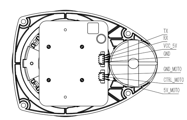
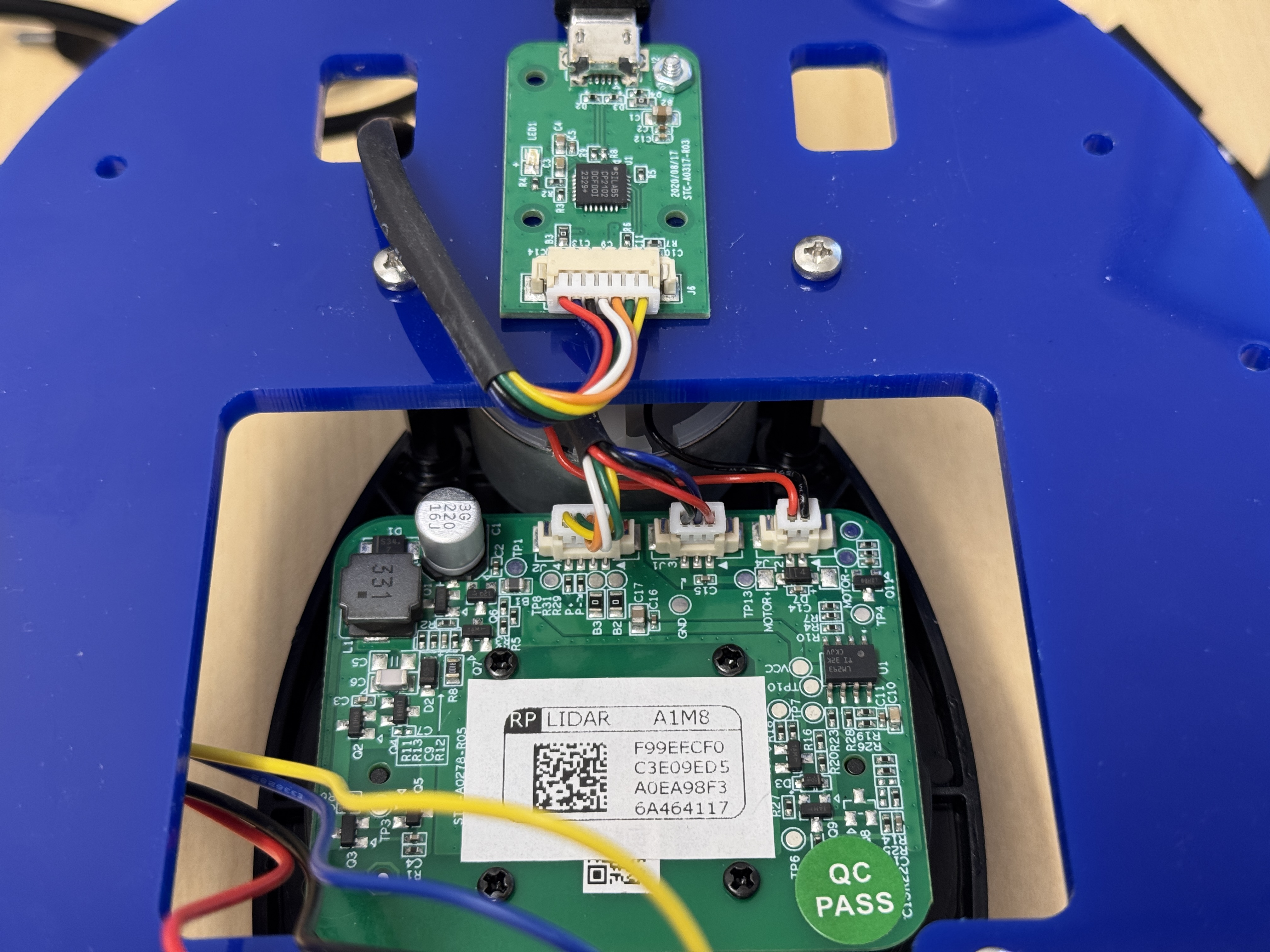
- Unplug the original 3-pin cable (the one marked by the green arrow in the image).
- Plug in the new cable from Step 1. The connector only fits one way. The colors shown in the image correspond to these pins, but your cable colors may be different:
- Yellow - GND
- Blue - CTRL
- Red - 5V
That’s it for the top plate.
Final Wiring
Now go to the official MBot Wiring Guide and finish all the wiring.
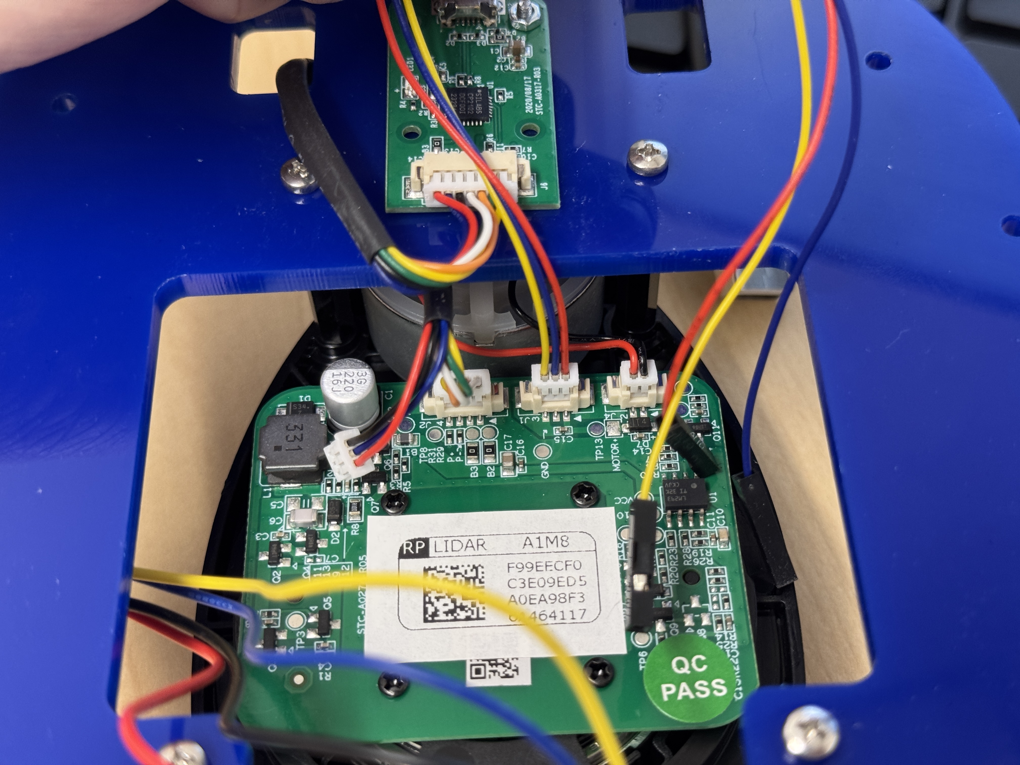
After that, also connect the LiDAR to the bottom board:
- Find the
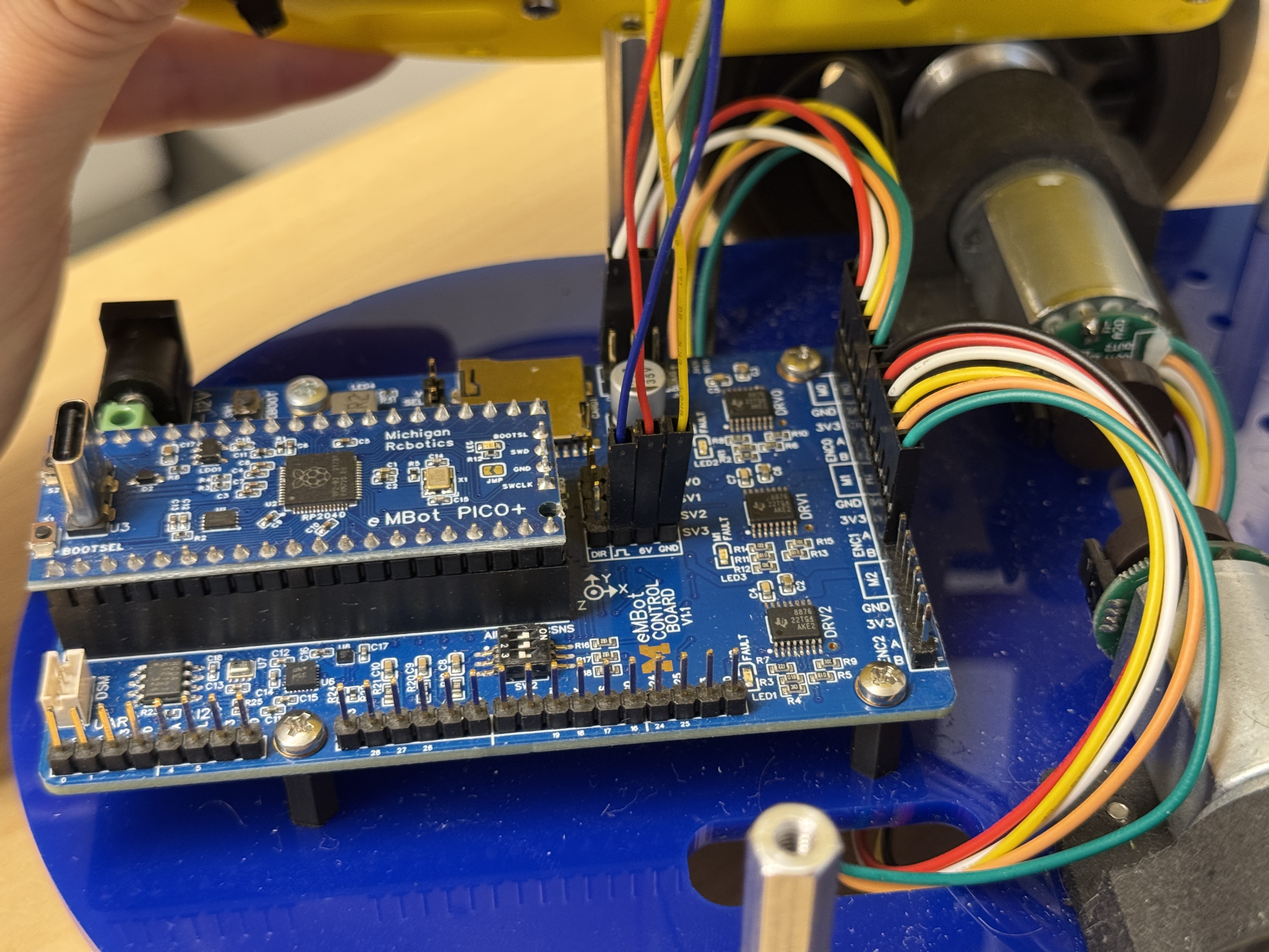
SV3slot on the bottom board (see image). - Connect each wire to the same signal used on the LiDAR board. In the example shown:
- Blue - CTRL (marked as
_|‾|_.) - Red - 6V
- Yellow - GND
- Blue - CTRL (marked as
Once assembled, complete the system setup by following the steps in the MBot System Setup.
Important: Do not power on the MBot before completing the system setup. The SD card you received might not be empty or could have the wrong operating system installed. Powering on the device before checking could damage the Raspberry Pi.
If you’ve already powered on the Raspberry Pi and notice the LED light has “4 long flashes followed by 5 short flashes”, it indicates a Fatal Firmware Error. You can find the solution in the troubleshooting guide here.