Camera Guide
Last Updated: Sep 02, 2026
This guide covers the RealSense camera in Armlab: how to check that it works, and how to find its intrinsic matrix with a checkerboard target using the camera_calibration.py tool. Everything here runs from the env550lab conda environment. There is no ROS in this lab.
Contents
- Contents
- Check the camera is detected
- RealSense Viewer
- What the intrinsic matrix is
- Prepare the checkerboard target
- Run
camera_calibration.py - Read the output critically
- Alternative tools
- Using the intrinsics in your code
- Common problems
Check the camera is detected
Plug the camera in and run:
rs-enumerate-devices -s
This prints the model, serial number, firmware version and the USB connection type. To confirm the Python bindings work:
python -c "import pyrealsense2 as rs; print(rs.__version__)"
The camera must be on USB 3.x. See Hardware. If this reports USB 2.1, try a different port and cable before asking an instructor for help.
RealSense Viewer
realsense-viewer is Intel’s GUI for the camera. Use it as your first diagnostic: if the stream looks correct in the viewer, the camera itself is fine and the problem is in your code.
realsense-viewer
User interface
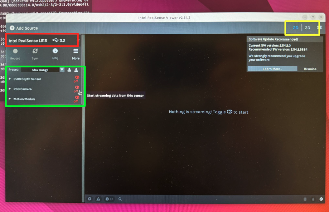
- Red box: camera model and USB version. Confirm USB 3.x here.
- Green box: the RGB and depth sensors. Both are off in this screenshot, so the view is blank. Toggle them on.
- Yellow box: 2D/3D view selector. Use 2D to check the raw streams; use 3D to eyeball the point cloud.
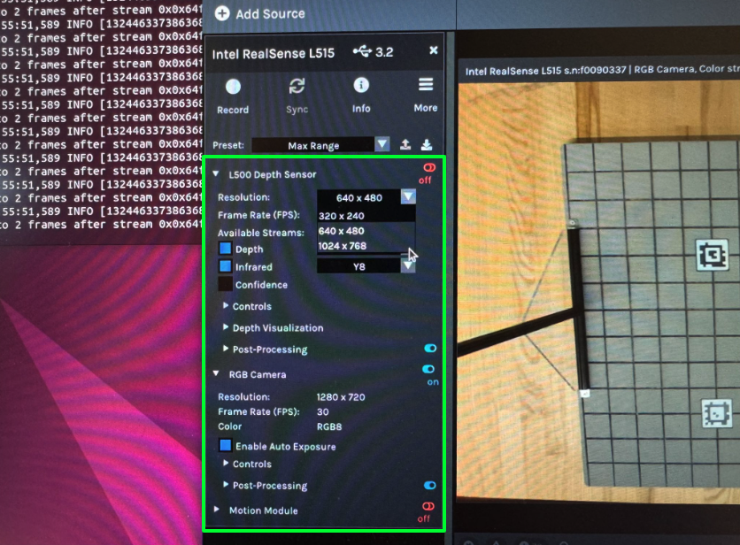
- With a sensor off, you can open its dropdown to see the resolution/frame-rate profiles it supports. You cannot change the profile while the sensor is streaming.
- The RGB camera above is on and streaming a checkerboard.
The screenshots above show the L500 Depth Sensor in the left panel, and that is this camera. The lab uses the Intel RealSense L515; see Hardware.
What to check when something is wrong
- USB version is 3.x (red box).
- Both the depth and color sensors turn on and produce a live image.
- The resolution profile you select in the viewer is one your code also asks for.
realsense-viewer keeps the device open, and so does camera_calibration.py. Only one process can hold the camera at a time. If something reports that the device is busy, close the viewer and check for a stale Python process before doing anything else.
What the intrinsic matrix is
The intrinsic matrix K maps a 3D point in the camera frame to a pixel:
fx,fy: focal length in pixelscx,cy: the principal point, roughly the image center
Alongside K you get distortion coefficients, which model how the lens bends straight lines. Together they let you convert between pixels and rays, which is what you need to turn a detected block into a 3D position.
K is only valid for the resolution it was computed at. If you calibrate at 1280×720 and then stream at 640×480, the intrinsics do not carry over. Recalibrate at the resolution you actually run at, or scale fx, fy, cx, cy by the resolution ratio.
Every RealSense also ships with factory intrinsics burned into the device, which pyrealsense2 will hand you on request. camera_calibration.py prints those alongside the ones it computes, so you always have a reference to check your own result against.
Prepare the checkerboard target
The calibration is only as good as the target, and this part is on you rather than the software.
- Print a checkerboard. A good default is 10×7 squares with 25 mm squares, which gives a 9×6 grid of inner corners.
- Print at 100% scale. “Fit to page” silently rescales it and every number you produce will be wrong.
- Mount it on something rigid and flat: foam board, a clipboard, stiff cardboard. A curled sheet of paper will quietly ruin the calibration.
- Measure the printed squares with calipers and use the measured value, not the nominal one. Ours print as 24.8 mm against a nominal 25 mm. Small, but it scales every distance the calibration produces.
- Matte paper if you have it. Glossy paper reflects the lab lights into the corners.
The tool needs the number of inner corners, not the number of squares. A board with 10×7 squares has 9×6 inner corners. Getting this wrong is the single most common reason the board is never detected.
The tool reads the board from three constants at the top of camera_calibration.py. Edit them to match what you printed:
BOARD_COLS = 9        # inner corners across (a 10-square-wide board has 9)
BOARD_ROWS = 6        # inner corners down   (a  7-square-tall board has 6)
SQUARE_MM  = 25.0     # measure one printed square with calipers
Run camera_calibration.py
The tool lives in your armlab repo at utils/camera_calibration.py, so you already have it, with no separate download. It is documented in the repo’s own README.md as well.
Close realsense-viewer first (it holds the camera), then run it from the lab environment:
conda activate env550lab
cd utils
python camera_calibration.py
A window opens with a live view of the color stream. The status line under the video tells you whether the board is currently visible, so you only ever keep frames the tool can actually use.
The window is built with PyQt5 rather than an OpenCV window. The lab installs opencv-python-headless, which has no GUI at all, so cv2.imshow does not exist in this environment.
1. Capture frames
Hold the board in view and press SPACE to keep the current frame.
| Control | What it does |
|---|---|
| SPACE | Capture the current frame |
| Undo last | Drop the most recent capture |
| Calibrate | Run the calibration, enabled once you have 10 frames |
| Q or Quit | Close the tool |
If the whole board is not visible, the frame is rejected and the status line says so. Nothing unusable ever enters the set. Accepted frames leave a faint outline on the live view, so you can see which parts of the image you have already covered and aim the next capture at a gap.
How to shoot a good set. This matters far more than anything in the software:
- 20 to 30 frames. Fewer than about 15 and the solution is poorly constrained.
- Tilt the board. Frames taken straight-on are nearly degenerate: they cannot separate focal length from distance. Aim for 20–45° of tilt in varied directions.
- Cover the whole frame. Put the board in each corner, along each edge, and in the middle. The distortion coefficients are determined almost entirely by what happens near the edges, so a set shot only in the center will not constrain them.
- Vary the distance, from filling most of the frame to roughly a third of it.
- Hold still. Motion blur moves the detected corners. Move, pause, then capture.
- Keep the whole board in frame. The detector needs to see every inner corner.
Move the board, not the camera, if the camera is already mounted at your station. It is the relative pose that matters, and you do not want to disturb a mount you will later calibrate against the robot.
2. Calculate the intrinsics
Once you have a good spread of frames, press the calibrate button. The tool runs the calibration over everything you captured and prints two sets of numbers to the terminal: the factory intrinsics read from the camera, and the calculated intrinsics from your frames.
==============================================================
  factory intrinsics (from the camera)
==============================================================
  resolution : 1280 x 720
  fx, fy     : 906.12, 905.88
  cx, cy     : 646.31, 358.04
  model      : Brown Conrady
  coeffs     : 0.00000, 0.00000, 0.00000, 0.00000, 0.00000

==============================================================
  calculated intrinsics (from 14 frames)
==============================================================
  resolution : 1280 x 720
  fx, fy     : 905.28, 900.30
  cx, cy     : 644.57, 355.21
  coeffs     : 0.00493, -0.07991, 0.00012, -0.00008, 0.39871
  RMS reprojection error : 0.076 px

  difference from factory:
    fx -0.84 px    fy -5.58 px
    cx -1.74 px    cy -2.83 px

  per-frame reprojection error:
    frame  0 : 0.044 px
    frame  1 : 0.026 px
    ...

  RMS is at or below 0.5 px - this is a good fit.
The two sets are printed side by side on purpose: the factory numbers are your answer key. The tool also flags any individual frame whose error is above 1.0 px, so you can undo it and recapture.
The numbers above came from synthetic test images, so that RMS is unrealistically low. On a real board expect roughly 0.1–0.5 px.
The result is also written to utils/camera_intrinsics.npz, next to the script, and the full path is printed. Load it with:
data = np.load("camera_intrinsics.npz")
K, dist = data["K"], data["dist"]
The control station does not read this file. camera.py takes its intrinsics from the camera at startup, so calibrating here does not change how the control station behaves. This exercise is about measuring the intrinsics yourself and being able to say how far the factory values can be trusted. To make the control station use your numbers, you have to load them in camera.py deliberately.
Read the output critically
Do not just copy the numbers down. Check them:
| Check | What you want to see |
|---|---|
| RMS reprojection error | Below ~0.5 px is good; above ~1.0 px means something is wrong |
| Calculated vs factory | Same ballpark. A large disagreement almost always means the inner-corner count or the square size is wrong, not that the factory is wrong |
fx vs fy | Within about 1% of each other for these cameras |
cx, cy | Within a few tens of pixels of the image center |
| Distortion coefficients | Small. The color stream is close to rectified already, so near-zero coefficients are expected rather than suspicious |
A low RMS error on a small or poorly varied set of frames is not evidence of a good calibration. It only means you fit a few similar views well. Coverage is what makes the result trustworthy. If your error looks great but every frame was shot head-on from the same distance, recapture.
Your calculated fx, fy, cx, cy land close to the factory values, with an RMS reprojection error below about 0.5 px, from a set of 20+ frames that covers the edges of the image as well as the middle.
Alternative tools
- ChArUco board: a checkerboard with ArUco markers in the white squares. Because each marker is individually identifiable, the board still works when it is partially out of frame or occluded, which makes capture much less fussy.
- MATLAB Camera Calibrator (
cameraCalibrator, Computer Vision Toolbox, available through the UMich license): a GUI that takes a folder of images, shows per-image reprojection error, and lets you drop bad images by clicking them. Useful as an independent cross-check of your numbers.
Using the intrinsics in your code
Read them at runtime
In your own code you can pull the factory intrinsics straight off the device:
intr = profile.get_stream(rs.stream.color).as_video_stream_profile().get_intrinsics()
print(intr.fx, intr.fy, intr.ppx, intr.ppy, intr.coeffs)
Align depth to color
Depth and color come from different sensors, so align them before indexing into the depth image, after which (u, v) means the same point in both, and the color intrinsics are the ones to use:
align = rs.align(rs.stream.color)
frames = align.process(pipeline.wait_for_frames())
color_frame = frames.get_color_frame()
depth_frame = frames.get_depth_frame()
Pixel to 3D point
depth_m = depth_frame.get_distance(u, v)
point = rs.rs2_deproject_pixel_to_point(intr, [u, v], depth_m)   # metres, camera frame
rs2_deproject_pixel_to_point uses whatever intrinsics you hand it. To use your calibration rather than the factory one, either overwrite intr.fx, intr.fy, intr.ppx, intr.ppy with your values, or do the arithmetic yourself:
\(X = \frac{(u - c_x) \, Z}{f_x}, \qquad Y = \frac{(v - c_y) \, Z}{f_y}, \qquad Z = \text{depth}\)
Common problems
| Symptom | Likely cause | Fix |
|---|---|---|
| The board is never detected | Inner-corner count wrong (squares counted instead of corners) | A 10×7-square board is 9×6 inner corners |
| The board is detected only sometimes | Glare, low light, or the board is cut off at the frame edge | Move away from direct light; keep the whole board in view |
| RMS error above 1 px | A blurred or badly-detected frame in the set | Recapture, holding still at each pose |
| Calculated values far from factory | Square size does not match the printed board | Measure the squares with calipers |
| Device busy / failed to open | realsense-viewer or another Python process still holds the camera | Close the viewer; kill the stale process |
| Stream fails to start at high resolution | Camera enumerated on USB 2.1 | Different port, different cable |
| Intrinsics look wrong in the control station | Calibrated at one resolution, streaming at another | Recalibrate at the streaming resolution |
The control station streams color at 1280 × 720 and depth at 1024 × 768, both at 30 fps, so calibrate at the color resolution it actually uses. See Software.